supermanotorious is FINALLY going solar!

The friendliest place on the web for anyone with an RV or an interest in RVing!
If you have answers, please help by responding to the unanswered posts.
Solar "trackers" are pretty much non-existent for RV rooftops (pretty impractical too) so I think you're probably talking about solar panel tilt kits. There are a variety of them on the market, but make sure you get the kind that allow the panels to be tilted to various angles. Some only allow panels to be adjusted to one pre-set angle, or they're flat.

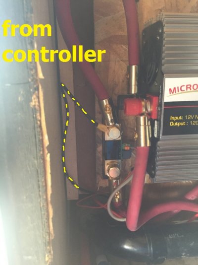
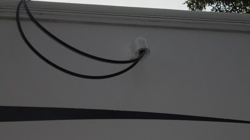
Running the wires is always the challenge. Fridge vents are common entry points, but I wouldn't hesitate to drill through the roof somewhere that would allow me to run the wires on a more asthetically pleasing path - especially if was a shorter distance to the controller. Dicor is your friend. :) However, if doing so meant that the wire run would be substantially longer, I'd have to think about that.

Kev
 
the run is going to be fairly long no matter what since the optimal place for the panels is the rear of the cabin while the controller is at the front, with that in mind the controller accepts 8ga max wiring, should I run 10ga from each panel 80% of the run, then in to a distribution block and 8ga for the remaining 20% run to the controller?
 
I'm not sure what components you're going to be using, or how you plan to wire the panels, but the lowest voltage in an RV solar setup is usually between the controller and the battery-bank, so that's where the wire run should be as short as possible, and where thick gauge wire should be used.

IMO, you should run the thickest gauge wire you can throughout your entire system. If your panels are going to be wired in parallel, voltage loss is going to be an issue on long wire runs, so thick gauge wire is going to be needed to reduce that loss.

Kev 
 
Here are the panels, charge controller, and monitor. The controller is close to the shunt, ground goes to the load side of shunt, shunt is on the 1/0 gauge run to the batteries approx 6' long, the controller positive goes to the master fuse for the batteries, currently both + and - are 10ga but I can easily upgrade them to 8ga. If necessary, I could run 8ga for each panel, in to a distribution block, then a single pair of 8ga to the controller but again, it's a lengthy run from panels to controller. Diagram below for the idea

PANELS X4: https://www.amazon.com/gp/product/B00V4844F4
CHARGE CONTROLLER: https://www.amazon.com/gp/product/B01B28RV96
BATTERY MONITOR: https://www.amazon.com/gp/product/B00MJ9TAN8

I do plan to mount the controller above the inverter which will allow for an even shorter run between the controller and shunt. The controller is wired to the shunt so the monitor can see what's going on, if I went straight to the batteries I'd have no idea.
 

Attachments

  • 009.1.jpg
    009.1.jpg
    132.1 KB · Views: 25
  • solar wiring.jpg
    solar wiring.jpg
    193.1 KB · Views: 28
That combination of equipment should work, but since you'll be using an MPPT controller, you might consider wiring your panels in series, or maybe every two panels in series. One benefit an MPPT controller has over a PWM controller is the ability to convert excess voltage to amps. That higher voltage will also help reduce voltage loss on the long wire runs you mentioned from the panels to the controller.

The panels you linked to put out a little more than 17 volts and about 5 & 1/2 amps (At max output.) That doesn't leave much for an MPPT controller to work with... to convert volts to amps. If every two panels were wired in series, however, you'd double the voltage going to the controller, which would extend the time the controller has each day to charge the batteries. They could all be wired in series if you wanted to. Helps during cloudy days too.

It appears that the controller does not have programmable (adjustable) voltage settings, so just be aware of that. Your batteries will get what the device is programmed to give them (Will probably be fine.) You should definitely use a shunt for the battery monitor - just ensure it's attached to the (-) battery terminal.

Kev
 
Rather than make another hole in my roof, I chose to enter from the side below the drip edge.
 

Attachments

  • DSC01219.JPG
    DSC01219.JPG
    33.2 KB · Views: 28
Kevin Means said:
That combination of equipment should work, but since you'll be using an MPPT controller, you might consider wiring your panels in series, or maybe every two panels in series. One benefit an MPPT controller has over a PWM controller is the ability to convert excess voltage to amps. That higher voltage will also help reduce voltage loss on the long wire runs you mentioned from the panels to the controller.

The panels you linked to put out a little more than 17 volts and about 5 & 1/2 amps (At max output.) That doesn't leave much for an MPPT controller to work with... to convert volts to amps. If every two panels were wired in series, however, you'd double the voltage going to the controller, which would extend the time the controller has each day to charge the batteries. They could all be wired in series if you wanted to. Helps during cloudy days too.

It appears that the controller does not have programmable (adjustable) voltage settings, so just be aware of that. Your batteries will get what the device is programmed to give them (Will probably be fine.) You should definitely use a shunt for the battery monitor - just ensure it's attached to the (-) battery terminal.

Kev

great advice, thanks Kev! the shunt is on the ground lead, but since it has a circuit board, I wanted it inside, not in the cradle underneath holding the batteries
 

Attachments

  • 018.JPG
    018.JPG
    149.5 KB · Views: 33
I moved the charge controller to above the inverter and I'm very happy with that. Now I have <12" run of 8ga with positive fused to the inverter terminals where "2/0ga" (more like 1/0ga) runs to the battery terminals. So Kevin, I'm hoping for very little voltage drop between the controller and batteries. I went to Consolidated Electrical Distribution right by my house and got 150' of HNNW 8ga for $63 after tax, should be about 20% more than I need. Now I need to either order or make the panel mounts, pick up some dicor, make all the connections, decide where to come through the roof, button it all down, and enjoy that system. But damned if I cant decide where to drop in.
 

Attachments

  • 032.JPG
    032.JPG
    303.8 KB · Views: 33
supermanotorious:

I ran into similar problems figuring out how to mount my system.  I used the fridge vent for wiring, which worked well on my unit as the cupboards where the converter was mounted were right beside  the fridge cavity.  I also had to figure out how to physically mount the panels to the roof.

If you haven't already, you may want to look at what worked for me here:

http://www.rvforum.net/SMF_forum/index.php/topic,106669.0.html

Frank.
 
thanks, I certainly did read that thread, took the trailer out near Willams, AZ this past weekend, kinda wished I had the panels installed, then we were hit with intense rain and hail and I was kind of glad the panels weren't exposed to that, I know I cant protect them forever but hey
 
then we were hit with intense rain and hail and I was kind of glad the panels weren't exposed to that

The resiliency of solar panels may surprise you.

I have just completed a large solar installation on our 2010 Arctic Fox 30U.  It rained shortly afterward, and we got  3/4" hail with it - loud enough to wake us up in the house.  Solar panels were all fine.

Frank.
 
What Frank said. There are international standards for solar panel construction, and hail impact resistance is one of them. Hail that's hitting hard enough to shatter a car's windshield, will usually have no affect at all on solar panels. Ours have been through a couple of hail storms, and suffered no damage whatsoever. They're tough!

Kev


Hail that's hitting hard enough to shatter a car's windshield, will usually have no affect at all on solar panels.


That is good to know. We get a lot of hail here, though seldom of windshield breaking size.


Frank.
 
I'm not concerned about weather anymore, I still haven't installed the doggone things and every trip involves putting them on the roof, connecting them, then bringing them back down, total PITA, for now she's on the driveway with all 4 panels resting on the roof, I am leaving the inverter on and it is powering a charger for my boat batteries, I am going to monitor for a couple days then may wire them to 24V to see if the controller converts the higher voltage to additional amps
 
finally made brackets and installed the panels, I sure hope the brackets were worth the pita, my plan is to someday replace the hardware with knob bolts so I can tilt the panels

I decided to run series/parallel for higher output voltage since the 8ga run from the panels to the charge controller is about 25 feet

used 3/4" long 14ga stainless screws to attach the brackets to the roof and sealed the footings with Dicor, ran the wires down the refrigerator vent, one reason I drug my feet on this was not realizing the refrigerator vent is basically just an open channel from the roof to the service panel for the refrigerator, I had the wires then follow the refig drain hose to the bottom of the coach then ran them along the frame to the controller
 
one reason I drug my feet on this was not realizing the refrigerator vent is basically just an open channel from the roof


Indeed, that is one of the great advantages of using that area for running wires. There's lots of room, and it is super easy to pull them through there.


Frank.
 
towed the rig to Winkelman Flats for the annual Riot on the River motorcycle event, the panels didn't blow off or come loose (phew). and of course Saturday was mostly overcast but I never saw the battery bank go below 90% and it was fully charged when I parked it on the driveway yesterday
 
I'm not sure how to configure the Victron BMV-700. My batteries are Interstate RC105    Ah: 20 hr @ 210 and I have 4 of them wired in series/parallel, what do I enter for total/desired amp hour?

System Voltage: 6V + 6V = 12V
System Capacity = 210AH + 210AH = 420AH  ?

ALSO, given these batteries, can anyone provide the values I should enter for Charged Voltage, Tail Current, Charged Detection Time, and Charge Efficiency Factor?
 
The combined AH for your battery bank is the 420 @ 12v. Once wired up, you have one big 12v battery, not 4 separate ones, and that's what the Victron sees.

For the other parameters, I'd go with the defaults until some experience is gained. The actual performance of your batteries and charger might eventually lead to some tuning changes, but changing them now seems premature to me. I would be tempted to move the Charged Voltage up a bit, but would want to see how it performs first. Most modern chargers get to about 13.6v at float charge, and the manual suggests setting the level 0.2v-0.3v below that.
 
Saturday was mostly overcast but I never saw the battery bank go below 90% and it was fully charged when I parked it on the driveway yesterday

I am looking forward to trying our new array in Arizona and SoCal, hopefully in a few weeks time.  We had it out once in August here locally, but parked in a shady campground.  Once I moved the trailer to a sunnier spot, we were fine.

Frank.
 

Latest posts

Forum statistics

Threads
131,915
Posts
1,387,345
Members
137,667
Latest member
awiltzius
Back
Top Bottom