You are using an out of date browser. It may not display this or other websites correctly.
You should upgrade or use an alternative browser.
You should upgrade or use an alternative browser.
Use frame for negative run
- Thread starter supermanotorious
- Start date
The friendliest place on the web for anyone with an RV or an interest in RVing!
If you have answers, please help by responding to the unanswered posts.
If you have answers, please help by responding to the unanswered posts.
xrated
Well-known member
It's been working in cars and trucks for the last 100 years or so. Having said that, you have to make sure that ALL of your ground connections are made on bare metal....and I mean bare! Files, emory cloth, small dremel bit, whatever you need to take the grounding locations down to bare metal. It wouldn't hurt to apply a dab of di-electric grease to the connection point also, just don't overdue it.
Cant Wait
Well-known member
If you look close to the wiring diagram you your unit I 'd bet you'll find that 90% of all negative runs use the frame instead of wasting the wire.
OP
OP
supermanotorious
Well-known member
that's what I was thinking too, although I've heard you want equal length runs for inverters
Isaac-1
Well-known member
It depends on how big the inverter is, It is much better to have a direct run of copper wire if it is a large inverter (over 800 watts or so)
OP
OP
supermanotorious
Well-known member
it is bigger, this is the 2,000 watt (4,000 peak) pure sine wave "solar" inverter
HappyWanderer
Well-known member
- Joined
- Apr 21, 2014
- Posts
- 2,967
Connections should be made directly to the battery, not dependent on chassis components to complete the circuit. Weird things start to happen when grounds are compromised. It's simply not worth saving the few bucks it takes to do it right.
Lou Schneider
Site Team
- Joined
- Mar 14, 2005
- Posts
- 13,249
A 2,000 watt inverter can draw up to 200 amps from the 12 volt batteries (400 amps during the 4000 watt peaks).
Are you absolutely sure your chassis connections can carry this load? How about any welds or joints between the connection points?
The other factor is voltage drop along the chassis rail. When the inverter draws lots of current through the chassis it will send voltage surges into other equipment that's also tied to the chassis rail. Things like the engine computer, radio, etc.
Arc welders use similar currents and can create the same kind of voltage surges, so it's common to disconnect the negative battery cable to protect the electronics before welding on a chassis.
All of the above is why you need to run both positive and negative cables from the inverter to the battery and leave the chassis out of the inverter's current path. And keep them short - even the largest wire will lose too much voltage if there's more than a few feet between the batteries and inverter.
xrated
Well-known member
supermanotorious said:In case I run out of cable, I could use what I have for the fused positive run, then use the frame to carry the negative from battery bank to inverter. Anyone see why this wouldn't work?
I totally missed where you are wanting to use the frame for the negative conductor for an inverter circuit. I definitely would not do that. It's a high current circuit and needs the proper size wire and the shortest distance possible from end to end to prevent voltage drop. Take Lou Schneiders advice.
AStravelers
Well-known member
As already stated, you want the absolutely least amount of voltage drop in the connection between the battery pack and the inverter. Use the proper copper wire size for the negative connection.
AStravelers
Well-known member
You also really need to install a battery monitor which displays the total AH (Amp Hours) going out of you battery pack and being put replaces by whatever charging method you use.
Use a Trimetric or something like it: http://www.bogartengineering.com/products/trimetrics/
Without a battery monitor like this you will not know just how far discharged and how close to fully charged your batteries are. You will be flying blind w/o the monior and WILL, over time, significantly reduce your battery life.
denmarc
Well-known member
I could not agree with Lou more! Cable the inverter directly to the battery using the correct gauge cable for the distance. And keep that distance as short as possible. Keep that inverter as close to the battery as possible. Even if you have to mount it somewhere you're not keen with. You will be happier in the long run and get the most benefit from it if you do. Trust me. I boondock 100% with genny power only to run the AC and charge the battery bank. Inverter runs electronics and such during the evening when silence is wanted.
Your idea is a good one. But the amperage that may be required limits your practical options.
Your idea is a good one. But the amperage that may be required limits your practical options.
OP
OP
supermanotorious
Well-known member
well I heeded the advice, I bought some legitimate 2/0 gauge pure copper welding wire for the runs which are approximately 8' long from battery bank to inverter
I'll post pictures of the wire run on my inverter project thread
I also thought I'd experiment with this battery monitor which should arrive later this week
https://www.amazon.com/gp/product/B013PKYILS
I'll post pictures of the wire run on my inverter project thread
I also thought I'd experiment with this battery monitor which should arrive later this week
https://www.amazon.com/gp/product/B013PKYILS
AStravelers
Well-known member
I assume you noted that the battery monitor is only rated for up to 100 amps and the inverter you listed earlier can pull 160-180 amps.supermanotorious said:well I heeded the advice, I bought some legitimate 2/0 gauge pure copper welding wire for the runs which are approximately 8' long from battery bank to inverter
I'll post pictures of the wire run on my inverter project thread
I also thought I'd experiment with this battery monitor which should arrive later this week
https://www.amazon.com/gp/product/B013PKYILS
fairway2002
Active member
A lot of modern day equipment use the chassis ground. If that inverter went bad it could put some weird voltage on ground. Might damage other equipment.
OP
OP
supermanotorious
Well-known member
AStravelers said:I assume you noted that the battery monitor is only rated for up to 100 amps and the inverter you listed earlier can pull 160-180 amps.
DOH!
BIG JOE
Well-known member
Just another .03 but...
For the purpose's of hooking up an Inverter correctly.. Connecting the Positive & Negative 12v supply leads [directly] to the Battery is the safest way to go. The Battery then becomes an RF Filter, a Heat Sink and has many other Whizo benifits.
Being sure the Inverter's body is connected to a good chassis ground.. is important also ?
")
For the purpose's of hooking up an Inverter correctly.. Connecting the Positive & Negative 12v supply leads [directly] to the Battery is the safest way to go. The Battery then becomes an RF Filter, a Heat Sink and has many other Whizo benifits.
Being sure the Inverter's body is connected to a good chassis ground.. is important also ?
Lou Schneider
Site Team
- Joined
- Mar 14, 2005
- Posts
- 13,249
AStravelers said:I assume you noted that the battery monitor is only rated for up to 100 amps and the inverter you listed earlier can pull 160-180 amps.
Not only that, but the amp-hour reading only counts up, not down. So you can meter how many amp-hours you're putting into the batteries, or how many you're taking out but not both.
It's a design flaw in those cheap meters. What you really want is an amp-hour meter that measures current flow both ways, in and out of the battery and keeps a cumulative count of how much remains. Otherwise you have no way of knowing the battery's state of charge.
robertusa123
Well-known member
I wouldn't cheep out on a nice inverter like that..... Do it right
OP
OP
supermanotorious
Well-known member
alright alright alright, I will return or resale the battery meter
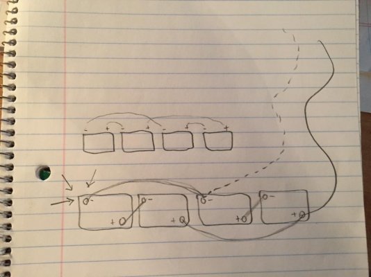
now, this diagram is how the batteries will be wired, any problem with the running the negative lead as depicted on the dashed line? the arrows in the left side of the image show where the negative run would normally come from but again, I'm trying to save wire, thoughts?
now, this diagram is how the batteries will be wired, any problem with the running the negative lead as depicted on the dashed line? the arrows in the left side of the image show where the negative run would normally come from but again, I'm trying to save wire, thoughts?