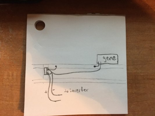
Use frame for negative run

The friendliest place on the web for anyone with an RV or an interest in RVing!
If you have answers, please help by responding to the unanswered posts.
supermanotorious said:
alright alright alright, I will return or resale the battery meter

now, this diagram is how the batteries will be wired, any problem with the running the negative lead as depicted on the dashed line? the arrows in the left side of the image show where the negative run would normally come from but again, I'm trying to save wire, thoughts?
I don't see anything wrong with the wiring.  No matter what you do you are going to have to have a jumper from one set of batteries going to the other.  To totally balance the wire lengths you would need to attach the + & - cables going to the inverter in the middle of the jumper.  If you had 4 sets of batteries I would want to make sure the cables to the inverter where in the center of entire battery pack. 

Here is a link to a great discussion about cabling multiple batteries together:  http://www.smartgauge.co.uk/batt_con.html 

Whether anyone agrees with or disagrees with the info in the above link, is not important.  The information given is worth considering.  We are all free to wire our batteries as we see fit.    I did not create the link or the info.  However I have seen some folks criticize some of the tiny details in the link. 
 
all these configurations are parallel, I have to use series/parallel to get 12V, I know for a fact I am wiring them correctly as this isn't my first install, however the question remains, any problem linking the negative out to the right side terminal rather than the left side terminal

AStravelers said:
I don't see anything wrong with the wiring.  No matter what you do you are going to have to have a jumper from one set of batteries going to the other.  To totally balance the wire lengths you would need to attach the + & - cables going to the inverter in the middle of the jumper.  If you had 4 sets of batteries I would want to make sure the cables to the inverter where in the center of entire battery pack. 

Here is a link to a great discussion about cabling multiple batteries together:  http://www.smartgauge.co.uk/batt_con.html 

Whether anyone agrees with or disagrees with the info in the above link, is not important.  The information given is worth considering.  We are all free to wire our batteries as we see fit.    I did not create the link or the info.  However I have seen some folks criticize some of the tiny details in the link.
 
AStravelers said:
I assume you noted that the battery monitor is only rated for up to 100 amps and the inverter you listed earlier can pull 160-180 amps.

wait a minute here

doesnt  Amps = Watts/Voltage  ?

so even at peak 4,000 watts / 110 volts (going low for arguments sake) = 36.36 Amps (repeating of course Leroy Jenkins)
 
supermanotorious said:
wait a minute here

doesnt  Amps = Watts/Voltage  ?

so even at peak 4,000 watts / 110 volts (going low for arguments sake) = 36.36 Amps (repeating of course Leroy Jenkins)

True, but we're talking about the 12 volt input.

4,000 watts / 12 volts equals 333 amps.  At the 2000 watts continuous rating it will pull about 160-180 amps.
 
doggone it, I didn't even realize that, this site is great for calculating

https://www.batterystuff.com/kb/tools/ac-to-dc-amperage-conversion-run-through-an-inverter.html
 
That's why cable lengths and gauge are so critical on the 12 volt side of the inverter.  Not only do you only have 1/10th as much voltage as on the 120 volt side, but you're running 10 times as much current at 12 volts.

Take both factors into account, and the 12 volt input is 100 times more sensitive to wire loss than at 120 volts.

That's why you need short, fat cables on the inverter input and having the path to each parallel battery be as equal as possible.  This means don't hang both cables on one battery and run more wire to the second battery, but put the (+) cable on one battery and the (-) cable on the other.
 
well in our Sandstorm, I ran 2ga wire about 5' long for our 1500W inverter with no monitor and it did just fine

this rig is getting a 2000W inverter and 8' runs of 2/0ga wire
 
supermanotorious said:
all these configurations are parallel, I have to use series/parallel to get 12V, I know for a fact I am wiring them correctly as this isn't my first install, however the question remains, any problem linking the negative out to the right side terminal rather than the left side terminal
Well, duh, yes, your 6V batteries are wired in series. This has nothing to do with whether or not this is your first install or your 20th install.  However as far as the link I provided goes, it does show parallel wiring.  Don't forget when you wire your pair of 6V batteries in series you just wind up with what in reality is a single 12V battery.  Your four 6V batteries are in reality are just treated as two 12V batteries.  If you had eight 6V batteries wired in pairs to form four 12V batteries you would match the diagrams in the link provided. 

I go back to my earlier reply:  "I don't see anything wrong with the wiring.  No matter what you do you are going to have to have a jumper from one set of batteries going to the other.  To totally balance the wire lengths you would need to attach the + & - cables going to the inverter in the middle of the jumper.  If you had 4 sets of batteries I would want to make sure the cables to the inverter where in the center of entire battery pack."
 
AStravelers said:
I go back to my earlier reply:  "I don't see anything wrong with the wiring.  No matter what you do you are going to have to have a jumper from one set of batteries going to the other.  To totally balance the wire lengths you would need to attach the + & - cables going to the inverter in the middle of the jumper.  If you had 4 sets of batteries I would want to make sure the cables to the inverter where in the center of entire battery pack."

On two parallel batteries (or two series strings of 6 volt batteries connected in parallel) wiring to opposite corners, i.e. (+) on one battery, (-) on the other, will balance the wiring.

Each set of batteries will see one jumper in the current path.  No need to split the jumpers in two to connect to the middle.
 
I have personally used the Victron battery monitors for decades and installed dozens of them. In my opinion, there are none better. Chuck
 
all wired up and everything is working as it should, pop on over here to see it:  http://www.rvforum.net/SMF_forum/index.php/topic,96811.msg925251.html#msg925251

turns out I didn't have to use the frame, the original cables to the tongue were long enough to reach the battery bank
 
we're in Zion and have been using the inverter as much as possible, charging batteries with the generator during the limited acceptable hours in the park

I def want an intelligent monitor now, and need solar and a wind turbine to aid with charging, Zion was windy as all get out last night!
 
You may want to re-think that wind turbine. My experience (on sailboats) says they are very noisy, and that there is a constant whine emitted that can be very annoying to you and your neighbours. The noise produced may vary between brands and types of generator though. They do not respect quiet hours unless you physically stop them from running.
 
Alfa38User said:
You may want to re-think that wind turbine. My experience (on sailboats) says they are very noisy, and that there is a constant whine emitted that can be very annoying to you and your neighbours. The noise produced may vary between brands and types of generator though. They do not respect quiet hours unless you physically stop them from running.

Agree.

Had one given to me.. I gave it away. To noisy.  Also agree that there may have been improvements between Then & Now though.
 

Latest posts

Forum statistics

Threads
131,964
Posts
1,388,317
Members
137,718
Latest member
urnwholesaler
Back
Top Bottom