Hi! I joined the forums because I hoped you folks could help me out here before I plunk $600 down for a new A/C unit...
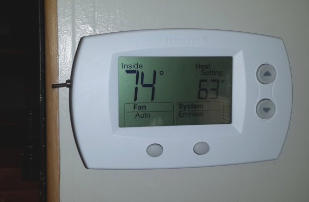
Here is what happened - Last night, we had lightning strike a tree about 50 feet from our travel trailer (2009 V-Cross Front Kitchen, 2 Slide outs, 32ft). It blew up not only the tree, but also the transformer box that was about the same distance away from the tree as our TT. They came later last night and replaced the transformer (after making our power flicker on and off a couple times - possible short??) and the A/C and Furnace would not function at all or make any noise while in auto-mode no matter whether the temperature slider was moved up and down. When I turned the fan switch (Duotherm Analag thermostat) to "ON" and flipped between hi and low fan speed, the fan works fine.
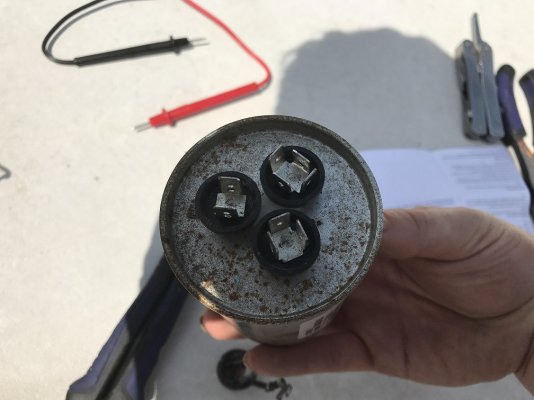
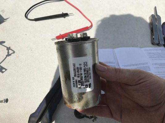
What I've done so far: I've found the repair manual online for duotherm and checked the compressor, and the capacitor (I think I did it right, but I don't really know much about using multimeters... I did at least figure out how to check continuity), and the overload thing. They all seemed to be normal, minus a black widow spider hiding in my capacitor area.... I pulled the thermostat off the wall and disconnected all the wires from it... Touching the green wire to the blue and orange makes the fan go hi and low (with both touching the green together), and touching the green and white makes the furnace/heater start up just fine. However, touching the green and the yellow (A/C) doesn't do anything at all. I haven't been able to get the red (7.5) wire do anything at all - what is that for?
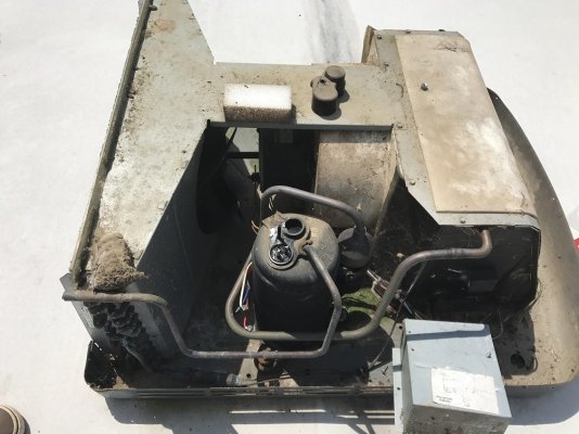
So, I'm rather confused - I had read all over that if you can bypass the thermostat then the A/C should run... but it isn't... And given that the thermostat wouldn't operator the furnace but using the wires makes it work leads me to believe that the thermostat is bad. I'm planning to run to walmart and get a new thermostat to try here shortly, but if you guys have any opinions or things I can check... I have the control box taken apart, but I don't see anything wrong with it... and I don't know how to check it either. I can upload pictures if that would help. Can't find a model number on the A/C - the paper is all faded.
Thanks!
Edited to say, I've been researching all day and can't find much that seems to help...
Here is what happened - Last night, we had lightning strike a tree about 50 feet from our travel trailer (2009 V-Cross Front Kitchen, 2 Slide outs, 32ft). It blew up not only the tree, but also the transformer box that was about the same distance away from the tree as our TT. They came later last night and replaced the transformer (after making our power flicker on and off a couple times - possible short??) and the A/C and Furnace would not function at all or make any noise while in auto-mode no matter whether the temperature slider was moved up and down. When I turned the fan switch (Duotherm Analag thermostat) to "ON" and flipped between hi and low fan speed, the fan works fine.
What I've done so far: I've found the repair manual online for duotherm and checked the compressor, and the capacitor (I think I did it right, but I don't really know much about using multimeters... I did at least figure out how to check continuity), and the overload thing. They all seemed to be normal, minus a black widow spider hiding in my capacitor area.... I pulled the thermostat off the wall and disconnected all the wires from it... Touching the green wire to the blue and orange makes the fan go hi and low (with both touching the green together), and touching the green and white makes the furnace/heater start up just fine. However, touching the green and the yellow (A/C) doesn't do anything at all. I haven't been able to get the red (7.5) wire do anything at all - what is that for?
So, I'm rather confused - I had read all over that if you can bypass the thermostat then the A/C should run... but it isn't... And given that the thermostat wouldn't operator the furnace but using the wires makes it work leads me to believe that the thermostat is bad. I'm planning to run to walmart and get a new thermostat to try here shortly, but if you guys have any opinions or things I can check... I have the control box taken apart, but I don't see anything wrong with it... and I don't know how to check it either. I can upload pictures if that would help. Can't find a model number on the A/C - the paper is all faded.
Thanks!
Edited to say, I've been researching all day and can't find much that seems to help...