Help ensure my inverter install looks good

The friendliest place on the web for anyone with an RV or an interest in RVing!
If you have answers, please help by responding to the unanswered posts.

Dooger54

Well-known member
Joined
Apr 4, 2016
Posts
73
Location
Central Illinois
I?m getting ready to buy and install an inverter for my TT and I?d like to confirm that my plans look good.  Yes, I have read the article here on inverter installations.  I?ve also read a ton of posts and watched numerous You-Tube videos. The inverter I plan to get will most likely be the AIMS 2000 watt pure-sine with built-in transfer switch.  The built-in transfer switch is 25 amp. Surge power is rated at 4000w.  AIMS recommends using 12 awg wire for the connections to AC power.  My run from the inverter to the back of my trailer to the power panel is about 20 feet.

https://www.aimscorp.net/2000-pure-sine-inverter-with-transfer-switch-etl-certified-conforms-to-ul458-standards.html

I will use the inverter mostly while boondocking.  I want to use it to provide power to my 120v receptacles and the 900 watt microwave.  The loads I will plug into the receptacles will be small fans, small TV,  1000w hair dryer for my wife, 700w toaster, 1400 watt coffee maker.  Obviously one at a time on the larger appliances.  My trailer has 30 amp service.  I am planning to pull (2) 15 amp.  breakers off the current main AC panel and move them to a new sub-panel.  One of these feeds the receptacles and the other feeds the microwave.

I will put a new 30 amp breaker in the main panel.  From that breaker I will run 12awg wire to the AC line-in of the inverter.  I will then run 12awg from the inverter AC line-out to the new sub-panel.  I am looking at buying a 60 amp panel (smallest I could find) with four breakers available.  I will install (2) 15 amp breakers and feed the existing runs from the receptacles and microwave to each breaker.

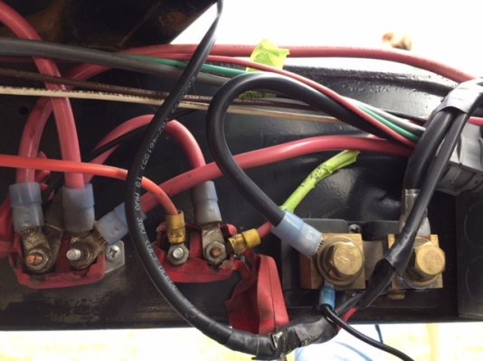
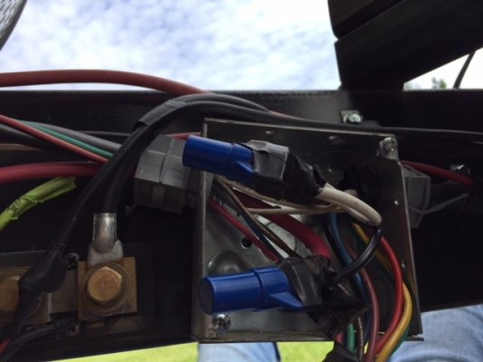
The negative cable from the inverter will go to the load side of my shunt, which feeds my Trimetric battery monitor.  The positive cable will go the the + battery terminal.  I do plan on putting an on/off switch and fuse in-line the positive cable.  These cables will be right at 10 feet long.

Am I missing anything or doing something wrong?

Recommendations needed for:

1) Size of battery cables?  2 minimum, maybe 0 or 00??
2) Size of fuse on the positive cable?


Thanks so much for helping!

 
At full load a 2000W inverter on 12 Volts is going to draw close to 183 Amps
that requires a battery bank of 700 Ah FLA or 350 Ah  AGM minimum.

you will need a minimum of 2/0 AWG copper cables and have them professionally made, most people do not have the tools for this job, get your local marine or golf shop to make them for you.

the fuse will be rated at 200 Amps.

your disconnect will be in the negative line before the shunt
your fuse will be in the positive line at or close to the battery.


Question:  A 25 amp transfer switch on a 30 amp circuit?  Somehow that doesn't sound right to me.

Sounds to me like that might be designed for use with a 15 or 20 amp inlet, and there may be a different model inverter with a higher rated transfer switch for use on 30 amp circuits.

Understand that I really don't know, but that just doesn't sound right to me.
 
The 25A transfer switch is fine on a device that draws a max of 2000 watts (sustained). That's only a max of about 18A (@ 110v). So is the 12 gauge 120vac input wire. However, you cannot use a 30A breaker to protect 12 gauge wire - it has to be 20A.  12 gauge wire has a max rated capacity of 20A and the breaker amps can never exceed the wire capacity.  If the breaker is larger than the wire, the wire fails (melts) first if there is an overload.

If you want to be able to provide for the full 25A capacity of the inverter's output circuits (2 x 15A), you need 10 gauge wire (rated 30A) for the 120v input instead of 12 gauge. Use the 30A breaker with 10 gauge.

You didn't mention batteries, and that is critical to inverter use. See solarman's advice.
 
Gary RV_Wizard said:
The 25A transfer switch is fine on a device that draws a max of 2000 watts (sustained). That's only a max of about 18A (@ 110v). So is the 12 gauge 120vac input wire. However, you cannot use a 30A breaker to protect 12 gauge wire - it has to be 20A.  12 gauge wire has a max rated capacity of 20A and the breaker amps can never exceed the wire capacity.  If the breaker is larger than the wire, the wire fails (melts) first if there is an overload.

If you want to be able to provide for the full 25A capacity of the inverter's output circuits (2 x 15A), you need 10 gauge wire (rated 30A) for the 120v input instead of 12 gauge. Use the 30A breaker with 10 gauge.

You didn't mention batteries, and that is critical to inverter use. See solarman's advice.

Ok, I will either go with the 10 awg wire and the 30 amp fuse, or switch to a 20 amp fuse and use the 12 awg.

Regarding batteries, I did note solarmans advice.  I only have (2) Trojan T105 batteries giving me a total of 225 amp hours capacity.  I understand his concern, but the only time we will use higher wattage is the coffee maker and hair dryer.  The coffee maker is 1400 watts, so it uses about 117 amps.  If we run it for 10 minutes in the morning to brew our coffee, we will use about 20 amps total.  So I wasn't concerned about the 225 amp capacity we have.  If I am thinking this through wrong, please correct me.
 
It's not so much the total amp hours, cause that only limits the amount of time you can use the inverter.  However, related to the AH capacity is the amount of voltage drop as the amp load increases.  The AH rating is at a very low amp rate, typically under 10A.  At higher amp rates, the capacity as well as the time to unacceptably low voltage is much less.  If you try to pull 117 amps from that size battery bank, the voltage will likely drop below the inverters low-limit before you get to the 10 minute mark.  In the real world it's not a cut & dried calculation, but I would guess there is a real chance your inverter will cut-off under some of the loads you described.

You also need to figure in the inverter efficiency loss. Depending on the inverter and the amp load, there is typically around a 5%-10% power loss doing the DC-->AC conversion. A simple rule of thumb is to add 10% to the theoretical amps.
 
This wire size calculator http://nooutage.com/vdrop.htm shows a 2.4% voltage drop with 2/0 wire at 10'.  The extra cost of 4/0 cable on a new install is not that much greater and would give you a 1.5% voltage drop.

The below figures are based on 150amp load and a totally full battery at 12.6V.  However as you use your battery the starting voltage will be lower than 12.6V.  Also as you put a 100-150amp load on the batteries you have a voltage sag of around 0.2 to 0.5 amps.  Hard to give an exact number, but when you get everything hooked up your Trimetric will show you exact numbers.

2.4% of 12.6V results in a 0.3V drop in the wire, resulting in the inverter only seeing 12.3V. That is not all that bad on a fully charged battery.
1.5% of 12.6V results in a 0.19V drop in the wire, resulting in the inverter seeing just over 12.4V.  That is better, but not really good.  This doesn't take in to account the battery sag under load.

This is why it is strongly recommended the battery/inverter distance is as short as possible.  Although you may not have a lot of options to locate the inverter closer than the 10'.
 
Gary RV_Wizard said:
It's not so much the total amp hours, cause that only limits the amount of time you can use the inverter.  However, related to the AH capacity is the amount of voltage drop as the amp load increases.  The AH rating is at a very low amp rate, typically under 10A.  At higher amp rates, the capacity as well as the time to unacceptably low voltage is much less.  If you try to pull 117 amps from that size battery bank, the voltage will likely drop below the inverters low-limit before you get to the 10 minute mark.  In the real world it's not a cut & dried calculation, but I would guess there is a real chance your inverter will cut-off under some of the loads you described.

You also need to figure in the inverter efficiency loss. Depending on the inverter and the amp load, there is typically around a 5%-10% power loss doing the DC-->AC conversion. A simple rule of thumb is to add 10% to the theoretical amps.

That makes sense.  Looking at Trojans website for this battery shows a Performance graph.  At somewhere over 200 amps it shows estimated time at about 50-60 minutes.  So this makes me think it can handle a load over 200 amps at least for a short time.  The highest amps the table shows for capacity is 75 amps and the estimated minutes are 115.  This is to maintain a voltage of at least 1.75v per cell.

Guess I can try it and if it doesn't work then we will have to run the generator.  I can step down to a 1000 or 1500w inverter but not sure what that will gain. 
 
Dooger54 said:
Regarding batteries, I did note solarmans advice.  I only have (2) Trojan T105 batteries giving me a total of 225 amp hours capacity.  I understand his concern, but the only time we will use higher wattage is the coffee maker and hair dryer.  The coffee maker is 1400 watts, so it uses about 117 amps.  If we run it for 10 minutes in the morning to brew our coffee, we will use about 20 amps total.  So I wasn't concerned about the 225 amp capacity we have.  If I am thinking this through wrong, please correct me.
Note that you don't have 225AH capacity.  That capacity is if you discharge your battery to 0% full.

If you discharge to 50% full you will have about 112AH. 

Keep in mind, Trojan rates their battery life at about 3000 discharge/charge cycles if the batteries are only discharged 25% (75% full) and if you go the 50% the life drops to about 1500 cycles, go to 80% discharged (20% full) the life drops to about 750 cycles. 

A lot is going to depend on your daily power usage.  If you main usage is brewing coffee and a hair dryer for a few minutes and little other usage during the day/nigh then you may be OK. If you have to run your gas furnace a lot on a cold night, that pulls a lot of power.  Again once you get everything set up, your Trimetric will give exact figures. 
 
AStravelers said:
This wire size calculator http://nooutage.com/vdrop.htm shows a 2.4% voltage drop with 2/0 wire at 10'.  The extra cost of 4/0 cable on a new install is not that much greater and would give you a 1.5% voltage drop.

The below figures are based on 150amp load and a totally full battery at 12.6V.  However as you use your battery the starting voltage will be lower than 12.6V.  Also as you put a 100-150amp load on the batteries you have a voltage sag of around 0.2 to 0.5 amps.  Hard to give an exact number, but when you get everything hooked up your Trimetric will show you exact numbers.

2.4% of 12.6V results in a 0.3V drop in the wire, resulting in the inverter only seeing 12.3V. That is not all that bad on a fully charged battery.
1.5% of 12.6V results in a 0.19V drop in the wire, resulting in the inverter seeing just over 12.4V.  That is better, but not really good.  This doesn't take in to account the battery sag under load.

This is why it is strongly recommended the battery/inverter distance is as short as possible.  Although you may not have a lot of options to locate the inverter closer than the 10'.

I can get it down to maybe 7-8 feet but that's about it.  Inverter is inside a storage compartment and the batteries are outside on the front frame of the trailer.  I may be able to get the positive shorter, but the negative has to be longer to reach the second battery.  But that would only be a difference of maybe 1-2 feet.  I've always assumed the battery lengths should be equal.
 
Since I am using the Trimetric I have to run the negative wire to the shunt, which is currently further away from the battery.  I may look at moving the shunt, but that brings up other issues with it.  I assume I will need to use the same gauge wire, 2/0 or bigger, going from the other terminal of the shunt back to the battery??
 
Dooger54 said:
That makes sense.  Looking at Trojans website for this battery shows a Performance graph.  At somewhere over 200 amps it shows estimated time at about 50-60 minutes.  So this makes me think it can handle a load over 200 amps at least for a short time.  The highest amps the table shows for capacity is 75 amps and the estimated minutes are 115.  This is to maintain a voltage of at least 1.75v per cell.

Guess I can try it and if it doesn't work then we will have to run the generator.  I can step down to a 1000 or 1500w inverter but not sure what that will gain.
I don't see a benefit to going to a 1000W inverter.  It won't power the microwave.  Even the 1500W is marginal for the microwave.  It is kind of like "I can always drive my car/truck at max power and max braking".  Yes you can, but it may not last as long.

I remember you have other topics on this forum, but I don't remember the details so I may be asking questions you have already covered.

To charge with your generator you MUST have a 3 stage charger and it must be mounted close to the batteries.  Voltage drop on long wires is significat.  Trojan wants about 14.7 volts for absorb charging, any thing else increases your generator run time.  You also want to be sure your charger has an equalize option.  You may want to go through an equalize cycle every month or two or every year, depending on how much you use your batteries and get them to 100% full.

If you discharge your batteries 40% (60% full) and run your generator about 2 hours with a 3 stage charger, you will get to around 90% full(maybe 85%).  The last 10%-15% may take 4-8 hours (or more) to get to 100% full. 

If you don't bring your batteries to 100% every few days to a week, you shorten the life of the batteries.  You may not be boondocking or dry camping that long so you could be OK. 
 
Dooger54 said:
Since I am using the Trimetric I have to run the negative wire to the shunt, which is currently further away from the battery.  I may look at moving the shunt, but that brings up other issues with it.  I assume I will need to use the same gauge wire, 2/0 or bigger, going from the other terminal of the shunt back to the battery??
The distance the Trimetric is from the battery doesn't matter.  The Trimetric comes with a 20-30 foot 3 or 4 wire cable.  It pulls very little current.  I assume the shunt is mounted right next to the battery.  If not, what is the reason.
Dooger54 said:
I can get it down to maybe 7-8 feet but that's about it.  Inverter is inside a storage compartment and the batteries are outside on the front frame of the trailer.  I may be able to get the positive shorter, but the negative has to be longer to reach the second battery.  But that would only be a difference of maybe 1-2 feet.  I've always assumed the battery lengths should be equal.
I don't think having one cable 1-2 feet longer than the other matters.  What would matter is if the batteries were separated by 2-6 feet then the loss from the cables between the batteries would come into play.  One battery would see a higher voltage than the other.
 
The specs for your 2000watt inverter, just being on, not powering any 120V devices, is 1.2amps of 12V continuously. That is over 25AH per day of your batteries 112AH usable capacity.  If you can get a remote panel to turn the inverter on and off that would be good.  If not be sure to go to the inverter to turn it off when not in use.
 
Well it looks as if the forum ate my post..?

so here it is again..LOL


2/0 cables were suggested as it fits the less than 3% loss rule

however, having learned of your T105's  ...cabling is now not the issue..

battery internal resistance takes over and you have the following issue with voltage drop.

A T105 has an internal resistance of approx 0.002 Ohms or 2 milliohms per cell

using this and computing for 2000 Watts full load ( actually 2200 allowing for inverter efficiency ) we get:

( 0.002 Ohms * 6 Cells ) *  ( 2200 / 12 ) = 2.2 Volts drop

assuming 100% SOC, and a new battery, your battery is now at 12.75 - 2.2 = 10.55 Volts
that's low enough to most likely trip the undervoltage lockout on the inverter.

this highlights the issue with low voltage systems...

if you keep the load to under 1500 Watts then you may get away with it for short bursts like 10 minutes.

at 1500 W your battery volts will be approx 12.75 - 1.5 Volts = 11.25 V and that should be ok

this doesn't take into account the cable losses.. so be cautioned..


FYI.  you shouldn't discharge a flooded battery at more than C/4 rate and an AGM at more than C/2

so for T105 gives a max discharge of 56 Amps and 112 Amps for AGM,  that's  672 and 1344 Watts respectivley

also you state the inverter is inside a storage compartment.. you had better ensure it's well ventilated, that inverter will get quite hot on load.


AStravelers said:
The distance the Trimetric is from the battery doesn't matter.  The Trimetric comes with a 20-30 foot 3 or 4 wire cable.  It pulls very little current.  I assume the shunt is mounted right next to the battery.  If not, what is the reason.

Reason is because there is a junction box on my trailer tongue that ties in various wires that go to the Trimetric.  I know that sounds vague but don't know how else to put it.  There are wires there that I have identified but I am not sure what would happen if I relocate them.  I have a diagram I have done up but it certainly doesn't conform to code standards so I don't know if anyone else than me can identify what I have done.  I have attached that and hope it can make some sense.  Please note the drawing is not to scale.  Please read the explanation at the bottom of the drawing.  Feel free to ask any questions and I will answer.
 

Attachments

  • Trimetric 2030 Wiring.pdf
    129.1 KB · Views: 0
  • trailer pic 1.jpg
    trailer pic 1.jpg
    72.9 KB · Views: 9
  • trailer pic 2.jpg
    trailer pic 2.jpg
    56.6 KB · Views: 7
AStravelers said:
The specs for your 2000watt inverter, just being on, not powering any 120V devices, is 1.2amps of 12V continuously. That is over 25AH per day of your batteries 112AH usable capacity.  If you can get a remote panel to turn the inverter on and off that would be good.  If not be sure to go to the inverter to turn it off when not in use.

I can get a remote pad for $20, so I will do that.  thanks!
 
solarman said:
Well it looks as if the forum ate my post..?

so here it is again..LOL


2/0 cables were suggested as it fits the less than 3% loss rule

however, having learned of your T105's  ...cabling is now not the issue..

battery internal resistance takes over and you have the following issue with voltage drop.

A T105 has an internal resistance of approx 0.002 Ohms or 2 milliohms per cell

using this and computing for 2000 Watts full load ( actually 2200 allowing for inverter efficiency ) we get:

( 0.002 Ohms * 6 Cells ) *  ( 2200 / 12 ) = 2.2 Volts drop

assuming 100% SOC, and a new battery, your battery is now at 12.75 - 2.2 = 10.55 Volts
that's low enough to most likely trip the undervoltage lockout on the inverter.

this highlights the issue with low voltage systems...

if you keep the load to under 1500 Watts then you may get away with it for short bursts like 10 minutes.

at 1500 W your battery volts will be approx 12.75 - 1.5 Volts = 11.25 V and that should be ok

this doesn't take into account the cable losses.. so be cautioned..


FYI.  you shouldn't discharge a flooded battery at more than C/4 rate and an AGM at more than C/2

so for T105 gives a max discharge of 56 Amps and 112 Amps for AGM,  that's  672 and 1344 Watts respectivley

also you state the inverter is inside a storage compartment.. you had better ensure it's well ventilated, that inverter will get quite hot on load.

All those calculations are beyond my expertise but I will take them as gospel, so thanks so much.  Maybe I need to step down to a 1000w inverter and forget the coffee maker and hair dryer, I can turn on the genny if needed.  Wonder if the 900 watt microwave will work on a 1000w inverter??

Either that or buy two more T105 batteries and double my capacity.  ;D
 
solarman said:
Well it looks as if the forum ate my post..?

so here it is again..LOL


2/0 cables were suggested as it fits the less than 3% loss rule

however, having learned of your T105's  ...cabling is now not the issue..

battery internal resistance takes over and you have the following issue with voltage drop.

A T105 has an internal resistance of approx 0.002 Ohms or 2 milliohms per cell

using this and computing for 2000 Watts full load ( actually 2200 allowing for inverter efficiency ) we get:

( 0.002 Ohms * 6 Cells ) *  ( 2200 / 12 ) = 2.2 Volts drop

assuming 100% SOC, and a new battery, your battery is now at 12.75 - 2.2 = 10.55 Volts
that's low enough to most likely trip the undervoltage lockout on the inverter.


this highlights the issue with low voltage systems...

if you keep the load to under 1500 Watts then you may get away with it for short bursts like 10 minutes.

at 1500 W your battery volts will be approx 12.75 - 1.5 Volts = 11.25 V and that should be ok

this doesn't take into account the cable losses.. so be cautioned..
I am unclear about your internal cell loss coming up with 2.2V loss. 

It seems like if I have 4 six volt batteries (12 cells) or 8 batteries (24 cells) I would have even more voltage loss than 2.2 volts.

Using your formula:  ( 0.002 Ohms * 24 Cells ) *  ( 2200 / 12 ) = 8.8 Volts drop and my 12.55V battery pack is now under 4 volts.  Yet with over 800AH of battery, a 2200 watt (180amp or 1/4C) load is not that significant.

Can you explain what I am missing? 

Also in your example of the end voltage being 10.55V would is that measured at the battery posts?

Is this formula a way to calculate the battery voltage sag under a load?  That is when you have high current draw from a battery the voltage drops some amount.
 
Dooger54 said:
Reason is because there is a junction box on my trailer tongue that ties in various wires that go to the Trimetric.  I know that sounds vague but don't know how else to put it.  There are wires there that I have identified but I am not sure what would happen if I relocate them.  I have a diagram I have done up but it certainly doesn't conform to code standards so I don't know if anyone else than me can identify what I have done.  I have attached that and hope it can make some sense.  Please note the drawing is not to scale.  Please read the explanation at the bottom of the drawing.  Feel free to ask any questions and I will answer.
Drawing didn't get attached.  I see the pictures of the shunt. 

Looking at the shunt, the cable from the battery side of the shunt is going to be replaced with the new 2/0 or 4/0 cable, and the new 2/0 or 4/0 cable from the inverter will attach to the other side of the shunt, correct.

As long as there is only one cable going from the battery side of the shunt to the battery and that is the only cable that attaches to the negative battery post, the Trimetric should read all the current going to the battery. 

Now if the Trimetric plus and minus leads don't attach close to the battery the voltage reading on the Trimetric will be lower by whatever voltage loss is caused by the length of the cables going to battery.  Mainly that will be significant when under a heavy current draw. 

Personally I would relocate the shunt to within a foot or two of the battery.  All you need to do is run your new 2/0 or 4/0 black cable from the junction box to the battery and relocate your Trimetric sense cables to the shunt.
 

Latest posts

Forum statistics

Threads
131,913
Posts
1,387,266
Members
137,665
Latest member
skibumbob
Back
Top Bottom