Building a new System

The friendliest place on the web for anyone with an RV or an interest in RVing!
If you have answers, please help by responding to the unanswered posts.
AStravelers said:
Thanks for the link.  Looks like a great link to a place to buy most any size metal you could want.  Should be much better selection than the big box stores.


These are the folks that cut up the brackets for me on my install. 2" x 1" aluminum angle cut in 4" lengths. I've used them for a number of projects  over the years, as we have one in Calgary as well.
 
As my overtime checks allow, I have been buying items for my project.  So far I have the inverter and remote, hardwired surge protector, battery monitor is coming today along with two Maxxair Maxxfan Deluxe units with remotes.  We purchased the fans with the hopes that they will keep the Camper comfortable enough so there will be no need for the AC.

Another question....
I read an article somewhere (can't seem to find it now) that one should have some protection between the alternator and the LiFePO4 Batteries so the alternator doesn't overheat and burn up.  It seems this would be more for Motor-homes but my Pickup does have a charge circuit to charge the trailer battery bank when towing.  If I remember correctly the article stated that the LiFePO4 batteries really suck up the juice fast and could damage the alternator.

Is this something that is needed to protect the tow vehicles charging system?  Also.. which one of these units (if either) is for that application; Precision Circuits LiFePO4 Battery Isolation Manager, or Precision Circuits Battery Guard?  It doesn't seem that the battery guard would be for this application.

 
I'm pretty sure that the charge circuit from your tow vehicle will have a fuse somewhere, so burning up the wiring is unlikely. There is also a fair bit of resistance on the long wire from the alternator to the battery in your trailer that will automatically limit how much current can flow.


With that said , I am no expert here. There may be current limiting devices that are recommended for this sort of thing, so I will step aside to allow those who DO know for sure to comment.
 
If you don't need the tow vehicle to charge the batteries, you can remove the fuse and disable the charge line until you get it figured out.
 
I don't think the article was referring so much about the amount of current draw, as Frank B stated, there is protection for that.  I think it was the length of time for the high draw that was the concern.  It was suggesting some sort of regulator that would stop the draw from the battery bank for a given period of time, let the alternator cool, then let it charge again.  Wish I could locate the article.

As kdbgoat stated, maybe just pulling the fuse is the easy answer.
 
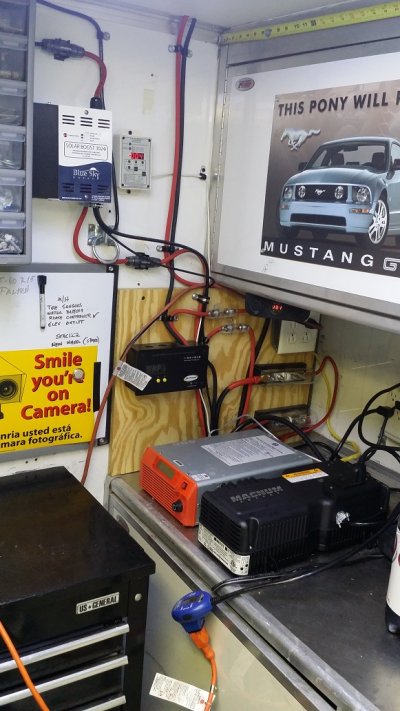
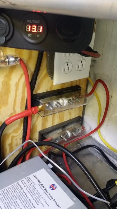
You may have already addressed it but you need a catastrophic fuse in the positive cable running from your batteries to your Inverter.


Attachments

  • r20160827_142401.jpg
    r20160827_142401.jpg
    211.4 KB · Views: 44
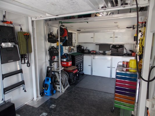
Gee Bill... you could have at least cleaned up your electrical compartment before posting that picture. The wood shavings in the corner are blocking our view of the fuse. :)

Kev
 
What did you expect for free pictures.

At least I zoomed in on the fuses so you did not see my whole messy workbench.
 

Attachments

  • r20160827_142422.jpg
    r20160827_142422.jpg
    233.2 KB · Views: 38
  • rshop2.jpg
    rshop2.jpg
    305.3 KB · Views: 39
Looks good, I ran a catastrophic fuse from each battery bank to a switch then goes to a common terminal block which then feeds all of my DC power needs including inverter; not just inverter.  With solar installations needing so many batteries, there is increased risk of electrical fire form a short.  All it takes is one wire to pull out of a crimped fitting or for road vibration to loosen a terminal lug.

If you have multiple batteries consider separting them into separate battery banks.  This allows me to perform equalization charges with my 4 stage converter regularly to balance the batteries.  It also allows me to use one battery bank as a spare incase of a short or issues in others.  I rotate battery banks so they remain exercised equally. 

Using a spare bank as a backup has saved my once.  I was towing on a fairly long trip to my camp site and my fridge was set to auto and  my electric heater 120 volt AC switch was accidently left one.  Unfortunately, I left the inverter on, and the fridge and water heater drew my batteries down to below 50% during the long drive in rainy weather.

Once I got back to my destination, I switched my backup bank on for power and let the original cells rest until the sun came out the next day so they could be charged separately by solar.  A little power management without having to run the generator got my back to 100% in 2 sunny days.


Kathy & Bill said:
Another question....
I read an article somewhere (can't seem to find it now) that one should have some protection between the alternator and the LiFePO4 Batteries so the alternator doesn't overheat and burn up.  It seems this would be more for Motor-homes but my Pickup does have a charge circuit to charge the trailer battery bank when towing.  If I remember correctly the article stated that the LiFePO4 batteries really suck up the juice fast and could damage the alternator.

Is this something that is needed to protect the tow vehicles charging system?  Also.. which one of these units (if either) is for that application; Precision Circuits LiFePO4 Battery Isolation Manager, or Precision Circuits Battery Guard?  It doesn't seem that the battery guard would be for this application.
At best you are only going to have #10 gauge wire from your alternator to your trailer and maybe not even #10 wire in the trailer, so you are not going to get much current down that small wire and whatever current you do get is going to have pretty good voltage loss along the way. 
Take a look at this voltage loss calculator:  http://nooutage.com/vdrop.htm
From the calculator,  if your trailer battery is 20' from the alternator and you only run 10amps down the #10 wire you will have a voltage loss of about 0.5V.  So if your alternator is putting out 14.0V you will only see 13.5V at the battery.  If you manage to get 20amps down the wire you have a loss of about 1V so the battery will only be seeing 13.0V.  That is not enough to charge the battery.

If the wire run is longer or the amps are greater, you will see even less voltage at the battery.
 
AStravelers said:
At best you are only going to have #10 gauge wire from your alternator to your trailer and maybe not even #10 wire in the trailer, so you are not going to get much current down that small wire and whatever current you do get is going to have pretty good voltage loss along the way. 
Take a look at this voltage loss calculator:  http://nooutage.com/vdrop.htm
From the calculator,  if your trailer battery is 20' from the alternator and you only run 10amps down the #10 wire you will have a voltage loss of about 0.5V.  So if your alternator is putting out 14.0V you will only see 13.5V at the battery.  If you manage to get 20amps down the wire you have a loss of about 1V so the battery will only be seeing 13.0V.  That is not enough to charge the battery.

If the wire run is longer or the amps are greater, you will see even less voltage at the battery.

I think I'll just pull the fuse if I notice a problem.
 
HueyPilotVN said:
You may have already addressed it but you need a catastrophic fuse in the positive cable running from your batteries to your Inverter.

Yes... I will definitely have a catastrophic fuse.
 
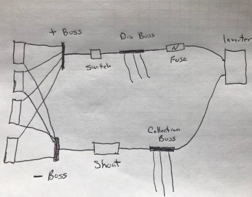
I'm in the process of placing an order for some of the smaller components; switch, battery fuses, buss bars and the catastrophic fuse.  I'm wondering what the proper sized catastrophic fuse should be for the inverter?  I have a Xantrex Freedom XC-2000.  The data sheet states that the DC nominal current at full load is 192 Adc.  The Buss bars I'm looking at are rated at 250 amps continuous load.  I'm thinking I'll end up with 3 or 4 LiFePO4 Batteries wired and fused as Solarman suggested.  Each battery fused and wired separately; to a buss bar, then a switch, then distribution buss, then catastrophic fuse and then to the inverter.  Negative side would be; from the inverter to a collection buss, to the Shunt, to the battery buss.

A ruff (and I mean Ruff) drawing attached.
 

Attachments

  • Proposed RV DC system.jpg
    Proposed RV DC system.jpg
    91.7 KB · Views: 24
I would just put a CB/switch like this:  https://www.bluesea.com/products/7149/187-Series_Circuit_Breaker_-_Surface_Mount_200A in place of the switch you have coming off of the plus buss bar.  I don't think there is a need for another fuse/CB between the buss bar and the inverter.

Be sure to size the heavy gauge cables going to the inverter & batteries with a wire size calculator. Try to size the cable for a 1% voltage drop.  Some places say 3% is OK, but the extra cost of the cable to go to 1% is not that much more than 3% and you will get much better efficiencies.  Note that some calculators only calculate for the length of cable you provide while others calculate for the round trip length.  You need to calculate the round trip distance (plus & minus length).

 
Kathy & Bill said:
I'm in the process of placing an order for some of the smaller components; switch, battery fuses, buss bars and the catastrophic fuse.  I'm wondering what the proper sized catastrophic fuse should be for the inverter?  I have a Xantrex Freedom XC-2000.  The data sheet states that the DC nominal current at full load is 192 Adc.  The Buss bars I'm looking at are rated at 250 amps continuous load.  I'm thinking I'll end up with 3 or 4 LiFePO4 Batteries wired and fused as Solarman suggested.  Each battery fused and wired separately; to a buss bar, then a switch, then distribution buss, then catastrophic fuse and then to the inverter.  Negative side would be; from the inverter to a collection buss, to the Shunt, to the battery buss.

A ruff (and I mean Ruff) drawing attached.

the battery positive bus and the distribution bus can be one and the same.

delete the fuse as drawn, replace the switch with a bussman or similar resettable fuse or "breaker"
for 192 amp full load you will be using at least 3/0 awg  to the inverter and will need a 250 amp breaker.

note: the fuse or breaker is there to protect the cable not the inverter !
also I would suggest a battery disconnect on the negative side by the shunt.

for powering smaller loads, these low cost fuse blocks actually work really well..


https://www.amazon.com/WUPP-Blade-Warning-Indicator-Damp-Proof/dp/B07GBST5NX/ref=pd_day0_hl_263_4/131-3829022-9020408?_encoding=UTF8&pd_rd_i=B07GBST5NX&pd_rd_r=b77078dd-3583-11e9-80dc-db96b6b7be1a&pd_rd_w=ns6xL&pd_rd_wg=dxPf9&pf_rd_p=ad07871c-e646-4161-82c7-5ed0d4c85b07&pf_rd_r=N6GJV3G8W8FDCT44SYK2&psc=1&refRID=N6GJV3G8W8FDCT44SYK2


if i get a few minutes tomorrow i'll rough draw you a suggested layout for comparison..
 
Kathy & Bill said:
That would be great and appreciated...

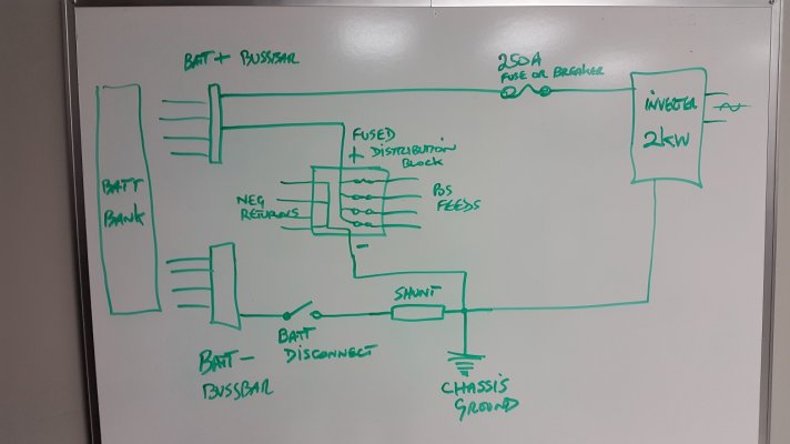
ok, i had a few minutes to draw this on my board.. it's quick and dirty, but you
will see the general format of things.
 

Attachments

  • basic wiring example.jpg
    basic wiring example.jpg
    193.6 KB · Views: 39
solarman said:
ok, i had a few minutes to draw this on my board.. it's quick and dirty, but you
will see the general format of things.

Very good, thank you much solarman.  I forgot about the chassis ground in my planning.  Hopefully I would have remembered when I was putting everything together.

Having a little trouble finding a 250 amp breaker that also can be used as a disconnect.  I found this one; https://www.amazon.com/XSCORPION-CB250-Circuit-Breaker-Manual/dp/B00MR1LVZS,  but the reviews were not good at all.  This one; https://smile.amazon.com/gp/product/B06Y454WHC/ref=ox_sc_act_title_1?smid=ALHXFZX1L0DAX&psc=1,  seems good and has positive reviews but no manual button for disconnect.

Anyone have a resource for such a breaker/disconnect at 250 amps?
 

Latest posts

Forum statistics

Threads
131,929
Posts
1,387,651
Members
137,677
Latest member
automedicmobile
Back
Top Bottom