You are using an out of date browser. It may not display this or other websites correctly.
You should upgrade or use an alternative browser.
You should upgrade or use an alternative browser.
2006 Honda Element Dinghy Set-up
- Thread starter BNTorsney
- Start date
The friendliest place on the web for anyone with an RV or an interest in RVing!
If you have answers, please help by responding to the unanswered posts.
If you have answers, please help by responding to the unanswered posts.
OP
OP
BNTorsney
Well-known member
KodiakRV said:I looked at the picture of your Element's front-end and said, "There's a fellow Floridian!"
[Lovebugs, for you outsiders. ;D ]
My wife told me to clean it before taking the photo, I prefer to fix things rather than clean them. I also know there is plenty of wax UNDER those love bugs - in good time, at least before we depart on RV2008, I will get "em" off!
OP
OP
BNTorsney
Well-known member
RV Roamer said:The Roadmaster diodes are rated for something like 50A at 12V, so no worries there. The diodes protect the toad's 12V system from being back-fed with 13-14V from the motorhome and exactly what that stops depends on how the toad's own wiring works. In general, without the diode you have a "wild" voltage looking for a place to ground and it may be reversing the normal polarity in the toad's 12v system. Sometimes it just lights up things that should be dead, but sometimes it has other side effects too. Placing the diodes in line stops any such worries.
This is a reply from Roadmaster's tech line:
I do not have a voltage rating but I do have a amprere load capacity, 85 amps.
Deanna Williams
Customer Service
[email protected]
5602 NE Skyport Way
Portland, Or 97218
503-288-9898 ext 105
800-669-9690
503-288-8900 fax
www.roadmasterinc.com
-----Original Message-----
From: Bruce N. Torsney [mailto:[email protected]]
Sent: Saturday, November 03, 2007 12:40 PM
To: [email protected]
Subject: lighting kit diodes
Please give me the voltage and current rating for these diodes.
Thanks,
Bruce
[edit]Removed extra spacing for easier reading[/edit]
Tom
Administrator
- Joined
- Jan 13, 2005
- Posts
- 51,906
BNTorsney said:... I do have a amprere load capacity, 85 amps.
Yep, same current rating that's in the Camping World ad I provided the link to. 85A is probably ultra conservative. IIRC I used 10A diodes on prior vehicles, before I bought the Roadmaster diodes for our current toad.
Karl
Moderator Emeritus
I could see using a high current diode like that if it were on a direct battery-to-battery charging circuit, but for lighting purposes, chances are they are already fused/c.b.'d at a much lower rating. That said, there's nothing wrong with using them, but I'd like to see a p.i.v. rating of 200 or more to protect against any inductive surges. Shouldn't be any, but you never know...
Tom
Administrator
- Joined
- Jan 13, 2005
- Posts
- 51,906
Agreed Karl. I seem to recall using diodes with a PIV higher than 200V, but that was a long time ago and my memory isn't that good. The reason I went with the Roadmaster diodes last time around was purely convenience and time; I remembered crawling under the Bronco with a soldering iron and heat shrink tubing, then decided a few crimp-on connectors to the Roadmaster spade connectors would be easier. IOW I was being lazy.
Ron
Moderator Emeritus
Maybe the high current rating is why they don't have many failures. The Roadmaster diodes we are using are 9+ years old.
Tom
Administrator
- Joined
- Jan 13, 2005
- Posts
- 51,906
The higher rating (usually turned around the other way and called derating) will definitely reduce the probability of failure of the diodes.
Ron
Moderator Emeritus
Tom said:The higher rating (usually turned around the other way and called derating) will definitely reduce the probability of failure of the diodes.
Yep and that is why I chose to use the Roadmaster diodes rather than another set that were actually cheaper. Been so long I don't even remember the brand or much about them.
Karl
Moderator Emeritus
Ron,
Roadmaster doesn't make diodes; they buy them from a semiconductor mfg'r. Anyone can buy 40-100A/200-400V diodes for about $1 apiece at Radio Shack or other parts suppliers (Allied Electronics, Newark, ad infinitum).
Roadmaster doesn't make diodes; they buy them from a semiconductor mfg'r. Anyone can buy 40-100A/200-400V diodes for about $1 apiece at Radio Shack or other parts suppliers (Allied Electronics, Newark, ad infinitum).
Ron
Moderator Emeritus
That is true Karl but the package them with their name on the package. Thus they are easy to identify and the apparently only package diodes that are capable and reliable for the purpose.
OP
OP
BNTorsney
Well-known member
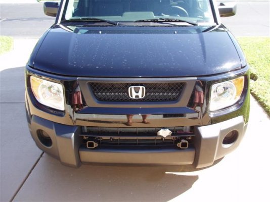
BNTorsney said:Before and After
These two photos are the before and after face-on photos of the Honda.
After reviewing this reply, I now realize in the "after" photo, it's hard to see the bracket because both it and the Honda are black. In the future, I will take another, more from the side photo and post it. I am beginning the preliminary wiring soon. This wiring is from the bracket mounted electrical socket, back to the dashboard. I can't finalize this project because I don't yet have the necessary diodes. Does anyone have an "Online source" for the 15A/60VDC diodes?
New face-on angeled photo without the Love bugs, the hard water spots can't be helped ;D
There will be a slight delay in the final wiring, I returned the 8 amp diodes for ones with a 1.5 to 2 times load current rating.
Attachments
OP
OP
BNTorsney
Well-known member
Here are the pointers you requested: (wire colors: first color given is wire color, second color is a stripe running the length of wire)petelakeland said:Just made my 03 Element a toad. Was on Blue ox and Roadmaster brackets. Wound up with the Roadmaster. Install time on the 1541-1 MX was three hours and fit perfect. No trimming body panels but had to angle a few wrenches. Have a Falcon II which is easy to use and folds up nicely. Also have a brake buddy which handles the brake lights but need to wire the tail lights and directional lights. Just not sure what kit to get or just go with magnet lights. Have been told it is more tedious work tracking wires,etc..... Give me some pointers once you complete... Thanks...
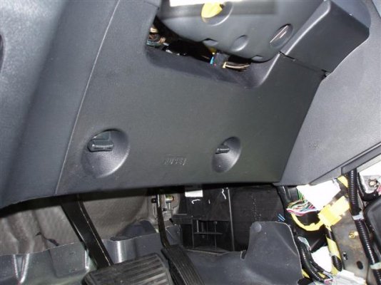
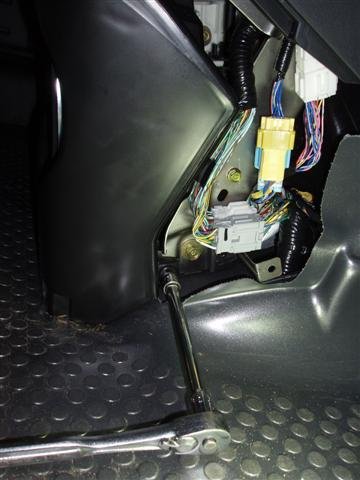
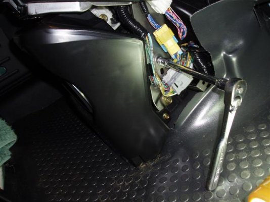
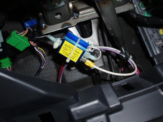
Remove the lower dashboard cover to reveal the brake pedal, brake light switch, photos 14 & 2. There is a 4 wire bundle, I have the white/ black wire separated from the others, it is at the bottom of photo 2; this wire is for the brake lights.
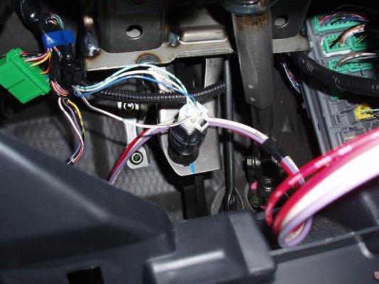
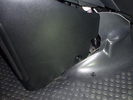
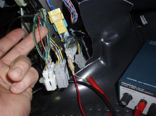
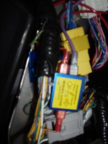
Remove, if your model has it, the bass woofer cover. There are two push-pins securing the bottom on both sides, photo 15. Push the center pin in about 1/8 inch and you will be able to pull the push-pin out. When they are both out, pull the cover toward the seat. There are 4 brass color bolts securing the bass woofer, two on each side, photos 12 & 13.; the electrical disconnect for this device is located drivers side, top. I have separated the three wires from the bundle. For the tail lights (red/yellow), LEFT turn signal (green/red) and RIGHT turn signal (green/yellow), photo 10.
NOTE: There are other wires with the same colors, the ones for the lights are the "heavier" gage wire.
When I receive my diodes, I will post where I made the connections.
Attachments
petelakeland
Member
Thanks for the update. I towed my E about 40 miles a last weekend and almost forgot it was there. Ford V10. It was during the day so i wasn't to worried about lighting. Brake buddy worked well although I need to up the sensitivity.
I will tag on your experience and ask what diodes did you get and where? Saw discussions about Camping world and will look back. Looks like your weekend is wired..
I will tag on your experience and ask what diodes did you get and where? Saw discussions about Camping world and will look back. Looks like your weekend is wired..
OP
OP
BNTorsney
Well-known member
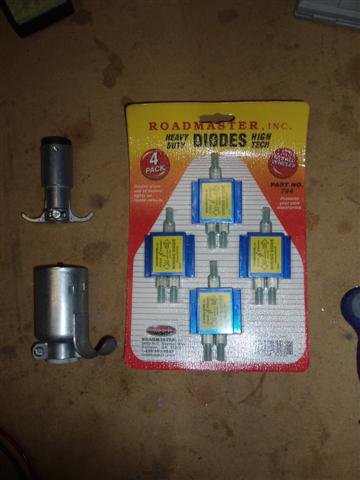
I only shop at Camping World when I have no other choice, they are expensive. I gave up trying to find the diodes I wanted and purchased Roadmaster's "Hy-power" diodes from Etrailer.competelakeland said:Thanks for the update. I towed my E about 40 miles a last weekend and almost forgot it was there. Ford V10. It was during the day so i wasn't to worried about lighting. Brake buddy worked well although I need to up the sensitivity.
I will tag on your experience and ask what diodes did you get and where? Saw discussions about Camping world and will look back. Looks like your weekend is wired..
http://www.etrailer.com/pc-Diodes~RM-794.htm
Attachments
Diodes are available at trailer stores almost anywhere. Form Supply stores, Auto Accessory stores, Part stores. They even come in kits with all the wiring, plus diagrams. Lets not make it harder than it is. The whole kit for all the wiring is only about 90 bucks. JMO
OP
OP
BNTorsney
Well-known member
Diodes Installed
I was able to install all four diodes without having to lengthen any of the OEM wires. I made my cut and crimped connectors on each end of the wire, installing a diode in the middle. In the second photo "Dinghy Lights (small)", there are three diodes stacked one on top of the other; these are for the tail lights, left and right turn signals.
Now all that is left to do is to make up a cable, with a six-pin plug on one end and a seven-pin plug on the other.
Attachments
OP
OP
BNTorsney
Well-known member
petelakeland said:Just made my 03 Element a toad. Was on Blue ox and Roadmaster brackets. Wound up with the Roadmaster. Install time on the 1541-1 MX was three hours and fit perfect. No trimming body panels but had to angle a few wrenches. Have a Falcon II which is easy to use and folds up nicely. Also have a brake buddy which handles the brake lights but need to wire the tail lights and directional lights. Just not sure what kit to get or just go with magnet lights. Have been told it is more tedious work tracking wires,etc..... Give me some pointers once you complete... Thanks...
The 1541-3 has a factory bracket located on the main brace for the electric, are you planning to use a 6 pin or 7 pin socket?
OP
OP
BNTorsney
Well-known member
Change in Plans
This being our first motorhome, I had heard some stories involving the "supplemental braking systems," that made me rethink my dinghy set up. The rear of the motorhome has a 7-pin socket and the front of the Dinghy had a 6-pin socket.
I have heard that after a "hard stop," sometimes the supplemental brake doesn't release the Dinghy brake pedal; it has to be done manually. There are radio transmitters included with these systems, that are suppose to notify the driver if this happens.
Not wanting to rely on "radio transmissions" to alert me, I decided to replace the Dinghy's 6-pin socket with a 7-pin model. This change will give me one extra wire. With this extra wire, I will "hardwire" from the Dinghy brake pedal switch to a light on the motorhome dashboard. If the supplemental brake should hang up, this light will let me know; sometimes the "OLD" ways are the best; more detailed photos to follow.
Our Apollo brake system uses a radio transmitter that is activated from the toad brake pedal so is independent of the Apollo itself and illuminates an indicator on the motorhome dash. I feel this is more reliable than a wire running the full length of the motorhome that can get broken. We test the system every time I install the Apollo as part of the hookup process. Sometimes the "new" ways really are better ")