hourmeter problems on generator

The friendliest place on the web for anyone with an RV or an interest in RVing!
If you have answers, please help by responding to the unanswered posts.

zonanavystar

Member
Joined
Jan 28, 2007
Posts
8
Hey,
  I have a champion 3500/4000 W generator that I'm trying to add an hour meter to.  It's a DC one from a marine store, so I hooked it up to the DC part of the generator.  Well after I mounted it and tried to run it, it didnt count the way its supposed to.  I hooked it up to a battery and it works fine, with the ticks every five seconds or whatever that interval is supposed to be with the white and black tick mark in the far right.  Sometimes it will just stop working altogether, and sometimes it works with no particular pattern.  I don't know what to do because the hour meter works just fine with the battery. 
 
The problem is the meter is a DC meter, the output of the portable generator is NOT DC, at best it is rectified AC, you might be able to make it DC

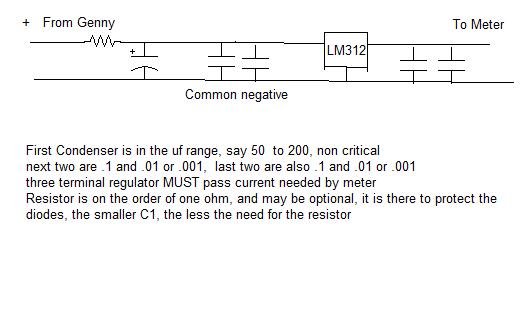
You will need a project box an LM-312 (or other 12 volt 3-terminal positive regulator) a small resistor (A diode may be indicated too) and a few smaller ceramic or titanium condensers  A lot of parts are optional, and possibly a power plug

I'd mount this on the back of the meter but here is the basic circuit

The input resistor is like one ohm, and may not be needed  (Larger input condensers use a resistor) it protects the alleged diodes inside the Champion generator

You may have to play with the input condensor a bit, I'd start with like 100uf  The other 4 should be two each .1uf and .001uf (one each size on each side of the LM-regulator)

If the meter works, Great, if not measure the voltage on the input condenser, if it's too low try doing away with the resistor, and then increase the size of the input condenser a bit

The LM should be at least a 1 amp type
 

Attachments

  • Basic 3-terminal regulator.JPG
    Basic 3-terminal regulator.JPG
    26.5 KB · Views: 8
I'm guessing you hooked the meter to the 12v outlet on the Champion?  John is probably right that this is most likely not pure 12VDC - more likely half-wave (rectified) AC stepped down to 12v. That would give you flaky results on a DC meter.
 
John,
I don't know where that schematic came from, but it won't work. The LM312 is an op amp; not a voltage regulator, and even if it was, it hasn't been in production since 1995. Attached is a circuit that will work using a LM7812, usually available at any Radio Shack as are the capacitors. Modify the input capacitor (C0) to 10uFd at 25 volts, and the output capacitor (C1) to 100uFd at 25 volts. It's o.k.to use higher voltage capacitors if they don't have them in 25 volt rating. The LM7812 is both input and output protected, so no additional components are needed. Note: the capacitors are polarity sensitive, so make sure the minus terminal goes to minus and the positive terminal goes to positive. Viewing the 7812 from the top side, the leftmost pin is the input terminal, the center one is ground (minus) and the rightmost is the output terminal. The packaging should show this too.

Also John,
and a few smaller ceramic or titanium condensers
I've never heard of a titanium capacitor. I think you meant Tantalum. ;)
 

Attachments

  • LM7812.doc
    26.5 KB · Views: 6
Northern Tool sells meters and tachs for small engines. Cheap, too.
 
Sounds good, I'll accept the mod and can modify the drawing (Though I'll leave the one here stand)

The idea is to use a 12 volt Positive 3-terminal regulator with about 1 amp of capacity or more
 
Back
Top Bottom