HWH Jack System Parts

The friendliest place on the web for anyone with an RV or an interest in RVing!
If you have answers, please help by responding to the unanswered posts.

Pubtym

Well-known member
Joined
Apr 20, 2009
Posts
444
Location
Brandon, SD
I have a 2006 Itasca Suncruiser Model 35 U. I, as well as others, hear and read posted horror stories of repair bills and operator challenges to keep four on the ground...or four stored. We all can agree...HWH has a fine design for the leveler jack system...but this discussion thread provides my research into some of their key system parts...and their documented high failute rates. Basically, a system is only as good as the quality and reliability of its parts. If alternative higher quality parts or part ideas exist, I try to provide them to you...

Before I get into specific parts..I need to provide some background information so we can all be on the same page..for considering specific issues with each part.

1. Industry Manufacturing Standards.The IP Code (or International Protection Rating[1], sometimes also interpreted as Ingress Protection Rating) consists of the letters IP followed by two digits and an optional letter. As defined in international standard IEC 60529, it classifies the degrees of protection provided against the intrusion of solid objects (including body parts like hands and fingers), dust, accidental contact, and water in electrical enclosures.[2] The standard aims to provide users more detailed information than vague marketing terms such as "waterproof". Let's focus on the first and second digets of the code..with special emphasis on the second didget.

http://en.wikipedia.org/wiki/IP_Code

2. HWH Information Bulletin, Jan 10, 2006.

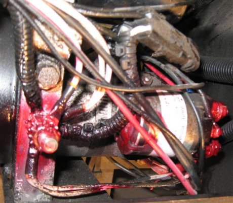
"Due to extreme weather conditions, exposed electrical connections can become corroded and deteriorated to the point of causing system failure in as little as one month of operation. On all vehicles, especially where exposure to road salts and deicing chemicals is common, all electrical connections should be protected from these conditions. Crimped and soldered connections should be protected with shrink tube. Ring terminal connections such as pump relay connections and frame ground connections should be thoroughly coated to provide protection."

http://www.hwhcorp.com/mi9554.pdf

3.The following is a quote from Drierite Website:

"Adverse Effects of Moisture"

"Water and water vapor probably cause more damage than any other contaminant, either by direct attack or by indirect means. Dampness can promote the growth of mildew or fungus. Water molecules on the surface of metals can cause rust, tarnish or corrosion. Water vapor in the atmosphere can promote chemical reactions which will corrode or destroy the material that comes in contact with the products of reaction. While the insides of a compartment or container and its contents may feel dry to the touch, a considerable amount of water may be adsorbed on the surface or in the pores of them. Changes in temperature can desorb the water and condense it into droplets causing water spots, localized corrosion or other deterioration. "
[edit]Added link to drierite.com[/edit]

More on specific HWH parts...and the relationship of the three paragraphs above?.....more to follow

 
The first HWH part I focus on is the Pump Relay Solenoid.  Chances are if you have not replaced the OE White Rodgers Solenoid..plan on it..
Remembering the three points listed above..I have a link to more information on this White Rodgers Solenoid. When you review the specs on it...note its Enclosure Rating (IP Rating).."Dust Resistant". Keep in mind this solenoid is openly exposed to some intense tire water spray and all the chemicals with that water..
http://www.grainger.com/Grainger/wwg/productIndex.shtml?from=Search&newSrch=yes&operator=keywordSearch&search_type=model&action=Go%21&QueryString=124105111&submit.x=21&submit.y=7

I changed my OE solenoid out today...as it was showing signs of failure..

Pictures posted show the solenoid and corrosion failures (contact pitting...) after I tore it apart to investigate.
 

Attachments

  • IMG_0464ss.jpg
    IMG_0464ss.jpg
    224.5 KB · Views: 157
  • IMG_0460ss.jpg
    IMG_0460ss.jpg
    181.5 KB · Views: 104
Added photos showing corrosion on the movable cylinder inside the coil...and corrosion/moisture tracks inside the solenoid case.

My next posting will cover what I replaced the White Rodgers unit with...think IP 66 and 67...

Charlie
 

Attachments

  • IMG_0459sss.jpg
    IMG_0459sss.jpg
    77.5 KB · Views: 63
  • IMG_0467sss.jpg
    IMG_0467sss.jpg
    77.6 KB · Views: 67
Contact pitting creates more resistance to current flow.. :mad:

"Free electrons tend to move through conductors with some degree of friction, or opposition to motion. This opposition to motion is more properly called resistance. The amount of current in a circuit depends on the amount of voltage available to motivate the electrons, and also the amount of resistance in the circuit to oppose electron flow. Just like voltage, resistance is a quantity relative between two points. For this reason, the quantities of voltage and resistance are often stated as being "between" or "across" two points in a circuit. "

http://www.allaboutcircuits.com/vol_1/chpt_2/1.html
 
WOW!  I'm surprised they used HWH jacks on your unit.....yours is the first gas powered 2006 Winnebago unit that I have heard of that have HWH jacks installed.....the rest of us have Kwikee/Power Gear jacks. :eek:

Well...thanks for the write up!  ;)
 
Good news..Trombetta has a direct crossover pump relay that is far superior quality than the White Rodgers unit...and about half the cost too.. ;D Check the IP rating on the Trombetta unit! ;) Made in USA!
http://www.trombetta.com/cm/pdfs/continuous-duty-powerseal-family.pdf

The Trombetta Part Number is 684-1211-012 ($27). The Hardware installation Kit for it is 33 cents..

I ordered mine from this link. I like to know exactly what I order and this link is a listed Trombetta distributor.
http://www.lvelectronics.com/

I made the pump relay swap out without difficulty. Major Caution: Disconnect all connections to the house and engine batteries before making any contact with terminals on the installed unit.

Pics below are of the Trombetta unit. Note the terminal torque requirements on the part label.
 

Attachments

  • IMG_0441sss.jpg
    IMG_0441sss.jpg
    54.3 KB · Views: 83
  • IMG_0443sss.jpg
    IMG_0443sss.jpg
    59 KB · Views: 62
Attached are pics of the installation. One photo is a bottom view of the relay and pump. Note the red goop preservative coated on the terminals as per recommendation of HWH Information Bulletin above.
 

Attachments

  • IMG_0450sss.jpg
    IMG_0450sss.jpg
    57.6 KB · Views: 109
  • IMG_0453sss.jpg
    IMG_0453sss.jpg
    81.1 KB · Views: 92
As I reviewed the many HWH system diagrams, one ground point is very critical to correct operations of most of the critical electrical componets controlling the system. That ground point is labeled-identified as: "The HWH Ground Stud" on the pump motor.

The photo with the red spray coatings show the HWH Ground Stud (left side of photo) following my first cleaning it with electrical contact cleaner spray then, protective coating it with battery terminal protection spray. The electrical component to the right of the ground stud is the pump relay mentioned by HWH in their Information Bulletin. Here, I have again cleaned and used protective spray on the relay terminals and connectors.

Note: When I checked the HWH Ground Stud top nut...I found it very lightly secured (tightened). I estimate about 10 pounds torque at most. After cleaning, I torqued the layered nuts on the post to about 20-25 pounds torque.
 

Attachments

  • IMG_0449ss (Small).jpg
    IMG_0449ss (Small).jpg
    65.2 KB · Views: 93
With my little knowledge of HWH jack-slide systems...I cannot find parts reference to an in line hyd filter....even though the system has a pressure pump and many other moving parts able to produce normal and common wear-tear micro-FOD...hmmmmm. Are the solenoid valve failures associated with micro-FOD (Foreign Object Damage)?

With added internet search...I found there are many companies that produce small cost effective mini in line high pressure hyd filters..One of these mini line filters should be able to be installed in the HWH hyd system...preferably on a line down fluid from the pump.....

More info here:

http://www.normanfilters.com/4200series.html[/quote]

After reviewing HWH hyd system drawings with a professional hyd repair shop, only one location could be considered to install a mini line hyd filter. Our discussion concluded it to be very difficult to fit a mini in-line filter into this line.

As an alternative to the line filter, the shop manager suggested dropping a magnet into the reservoir tank. This magnet would attract and retain small metal particles (micro FOD) so they will not foul any of the valves, switch, or jack tube parts.

I ordered magnets.
http://www.magnet4less.com/product_info.php?cPath=13&products_id=326

This magnet fits down through the tank's 5/8th inch fill hole. I wrapped several loops of #19 gage stainless steel wire around the magnet then fasten a 2 inch length of wire through the small holes in the dip tube portion of the breather plug (Tank Cap). This places the magnet suspended in the fluid so as to seize micro metallic FOD as it circulates through the tank. Finally, with the magnet attached to the wire from the Breather Cap, I can check the magnet...clean it as necessary, each time I check the tank fluid level.

Attached a photo of the ?dip stick? magnet and connecting wire.
 

Attachments

  • IMG_0436 (Small).JPG
    IMG_0436 (Small).JPG
    47.5 KB · Views: 81
After 20 miles driving and allowing the Hyd Reservoir tank fluid to slosh around the magnet...and with 10 cycles of the jacks and a few with the slides...the results of the magnet are in...not pretty! :eek:

To the left of the photo shows the dark gray metal micro FOD that has already attached to the magnet on the "dip stick" ...To the right of the photo is my telescoping magnet where swabbed the bottom of the reservoir tank...and the same dark gray metal micro FOD.

My point here is that without a filter type device...even a magnet...this junk circulates throughout the jack and slide..pump system and slowly chokes up.. tears down valve surfaces and switch seals...resulting in premature part failure.

Magnet in your tank anyone?
 

Attachments

  • IMG_0475 (Small).JPG
    IMG_0475 (Small).JPG
    60 KB · Views: 115
  • IMG_0474 (Small).JPG
    IMG_0474 (Small).JPG
    55.2 KB · Views: 93
Jim Godward said:
And to make it even worse, there is no recommendation to flush and drain the system EVER!   :'(

I think Power Gear recs a fluid change every two years.

I'm working on a flush method now...more to follow.. ;)

Charlie
 
Pubtym said:
I think Power Gear recs a fluid change every two years.

I'm working on a flush method now...more to follow.. ;)

Charlie

Potential "Time-Sert" solution to allow easy drain and flush of HWH Hyd reservoir tank.
I'm focusing on the drain kit # 0121C.
http://www.timesert.com/

Any member ever used Time-Sert stuff before. Many other mechanic-motorcycle threads praise the company's kits.

Charlie
 
I have used Keensert and Heli-Coil thread repair inserts, but not the Time-sert.  The Keensert locks into the hole by driving keys down into the base metal to securely lock the insert.  I have experienced the pain of having a Heli-Coil screw down into a cylinder (on a Porsche) requiring extensive repairs.

There is a type of insert that I cannot recall the name of that would work well on a thin-walled resevoir.  It has a knurled or knobby area at the top / outside that when it is installed to the correct depth is peened or flared outward to bite into the base metal to lock the insert.  We used these on thin-walled aerospace parts back in the early '70s.  They were liquid-tight.

 
No, they were very similar to the inserts the OP has linked, but instead of a flange perpendicular to the axis of the thread like the Time-serts, they had a mallable cylinder on the outside end that had teeth or bumps on the outside that we would stake out (flare, or peen out) that gripped the parent metal, locking them in place.  We always had a very specific countersink on the hole that the insert flare locked onto.  These were parts for the Atlas or similar era ICBMs.
 
Pubtym said:
Potential "Time-Sert" solution to allow easy drain and flush of HWH Hyd reservoir tank.
I'm focusing on the drain kit # 0121C.
http://www.timesert.com/

Any member ever used Time-Sert stuff before. Many other mechanic-motorcycle threads praise the company's kits.

Charlie

Thanks for added inputs on devices like Time-Serts.  After looking at thin wall of reservoir tank...I have aborted idea of polking a hole in tank bottom and "unskillfully" (Fat Fingered Fred) attempting install of a drain plug. ::)

Instead..late yesterday ....I put together a drill pump rig to suck the bad hyd fluid out..then replace...with fresh fluid. I'll try all today and post pic of my DIY flush rig..Cost of all about 10 bucks..

 
I believe the best thing to do if you really want a drain is to have a nut or fitting welded onto the bottom of the tank.  This would probably need to be a taper pipe fitting or a straight threaded fitting with an O-ring seal.  The resevoir should not have any pressure inside, but certainly the parts would be subject to corrosion, so should probably be stainless steel or at the very least powder coated.
 
I put together a drill pump drain kit to drain the hyd tank and refill with fresh Dextron III.  It worked extremely well..and it was simple and inexpensive. ;D
The amount pumped from the hyd tank wa 6 quarts...that's jacks up...slides in ..coach on level grond. The straight-stiff piece on the drill pump assembly is to stick in the tank. It is 1/2 inch PEX tubinig. That's so I could work the bottom of the tank with out tube worming in the tank. ;) Attached are photos.
 

Attachments

  • IMG_0478 (WinCE).JPG
    IMG_0478 (WinCE).JPG
    16.9 KB · Views: 82
  • IMG_0477 (WinCE).JPG
    IMG_0477 (WinCE).JPG
    17.2 KB · Views: 80
Here's pic of fluids. Dark fluid is from the Tank Reservoir. :eek: It has been in use about 3 years.. The measure cup has the fresh unused Dextron III for refill.
I think I'll go to a fluid flush-refill every two years. ;) Time to do all this..about 1 hour.

Cost: 18 dollars Dextron III (6 quarts-Super Tech-Walmart) ;D
 

Attachments

  • IMG_0479 (WinCE).JPG
    IMG_0479 (WinCE).JPG
    17.9 KB · Views: 88

Latest posts

Forum statistics

Threads
131,929
Posts
1,387,651
Members
137,677
Latest member
automedicmobile
Back
Top Bottom