2009 Winnebago Destination 37G ? adding front TV
Part three of this project ? the mounting of the TV bracket
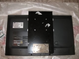
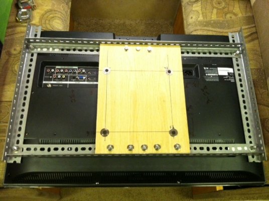
The TV mounting bracket ? the section that attaches to the TV proved to be the most challenging. The mount bracket is designed for a Sharp LCZ6D43U 26 inch LCD. Physical dimensions of the Sharp TV are 26x18x3. It also has a VESA 100x100 mount. I choose a Samsung LED LCD, model UN26D4003. This TV is slightly smaller, but the main difference is a VESA 200x100 mounting area. This meant that I had to adapt it down to a 100x100. To do this I used two pieces of ? x1/8 flat aluminum, each about 9 ?? long. I drilled two holes in the center of each strip, matching the factory mount and put in #10 x 1? bolts. I connected the flat aluminum to the TV using industry standard M4x70mm bolts.
During the lay-out of the mounting bracket to the TV, I noticed that the TV attach point were relatively high on the TV. The mounting holes in the bracket, designed to match the slots on the main support, seemed to indicate that the mount of the Sharp LCD TV was more on center on the TV. If I were to use the ?factory? holes on the bracket, then the TV would be low, well below the cabinet bottom. Since there was space on the TV bracket, I drilled another set of holes higher on the bracket. This way the TV would mount to the main support toward the top. Making this modification of course caused two, later to be three other problems. First, on the bottom of the TV bracket was a second square hook, which looked like it was designed to catch and support the bottom edge of the TV. This hook rested against the back of the TV I was trying to install. Choice was to cut this support hook off. As I examined the TV bracket, I noticed that the support hook on the bottom was a separate piece of steel that was riveted and spot welded on the TV bracket. I drilled the rivets out, then drilled the welds and took a cold chisel and used it and a hammer to separate the pieces. OK, one problem solved, the next one was that the TV bracket obstructed the antenna connector on the TV. This I solved by drilling a 1/2? hole through the TV bracket where the antenna connected. Now problem two was solved.
Problem three was that the new mount holes for the TV in the bracket did not line up with the slots in the main support, so the TV would not attach to the main support. Now I was at a little disadvantage. First, I had already screwed the main support to the cabinet, so I did not want to take it out. Second, the motorhome is about four miles from my home/garage where all the heavy duty power tools are. So, after making a trip back home to get big drill bits, I drilled two holes in the main support where the bolts from the bracket would go. This allowed the TV bracket to mount on the main support ?as designed.?
Things looked good, until I discovered that the main support also covered the antenna connector. All the other connectors were free and clear, except the TV connector. Back to the drill, another hole, closer to ?? was made in the main support to allow the antenna cable through to the connector.
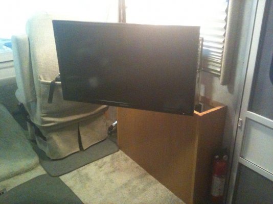
So, I then aligned the bottom holes of the bracket with the holes in the main support, put in two screws, attached the power cable, and I was ready to test. To make sure that I did not have a viewing angle problem, I spaced the top of the TV bracket away from the TV with some washers. This gave the TV a downward tilt.
So, now I have to put some trim along the edges of the cabinet to hide the opening that was not covered by the TV. I think that I have some stock left over from the kitchen remodel of the S&B that matches pretty closely to the finish on the motorhome cabinets.
Cost wise ? the mount cost about 2/3rds the cost of the TV. Would I go the same route in the future (using the ?factory?) mount? Maybe. One thing for sure, it was nice having steel components that for the most part fit right out of the box. This in itself reduced fabrication time.
I?ll post pictures with the trim in place when I complete it. Be a couple weeks as work will be getting in the way of play and travel.
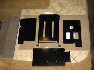
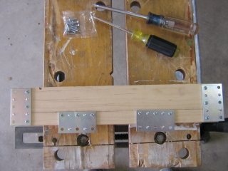
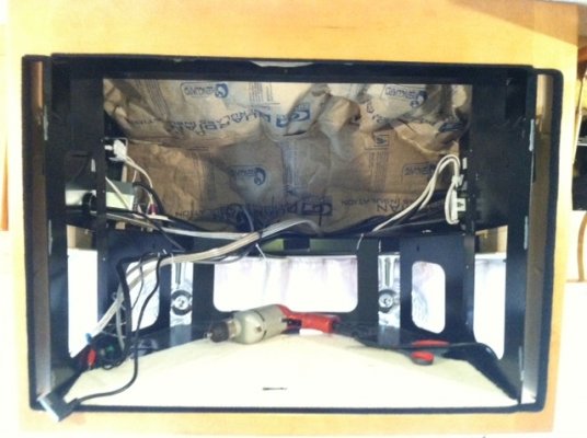
Photo one ? Adapter ? 200x100 to 100x100 mount
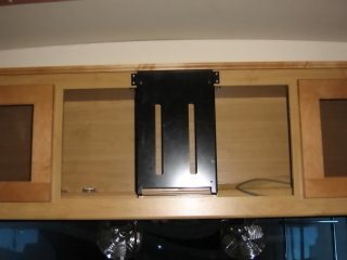
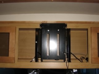
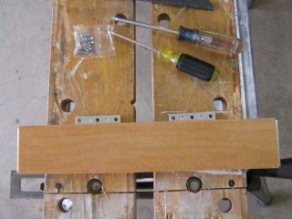
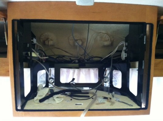
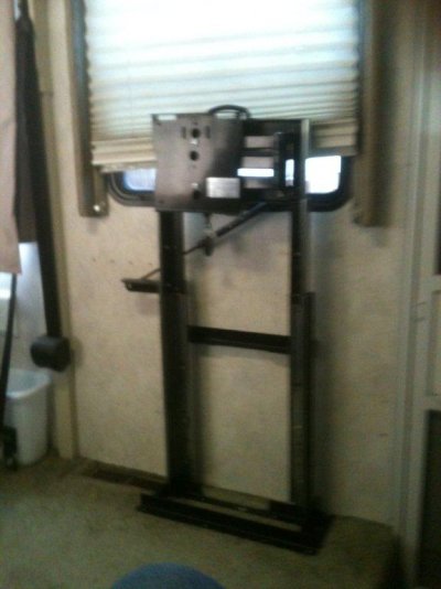
Photo two ? TV bracket, attached. Lower hook removed and hole for antenna cable
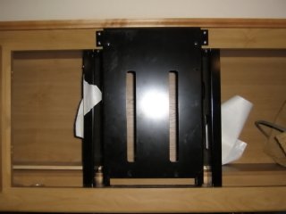
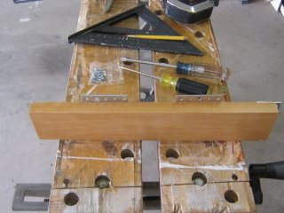
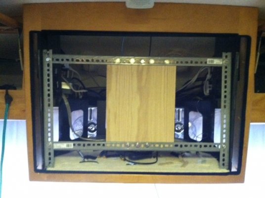
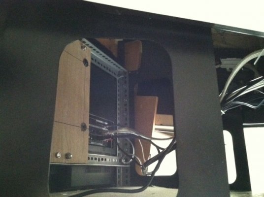
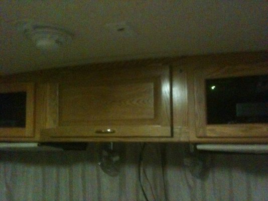
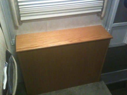
Photo three ? Main support with holes drilled to accommodate upper bracket mounting bolts and antenna cable
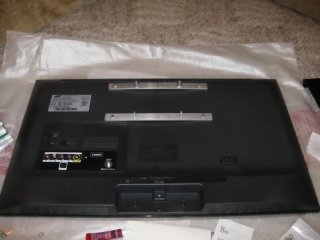
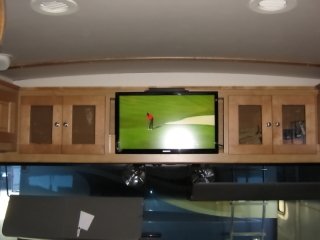
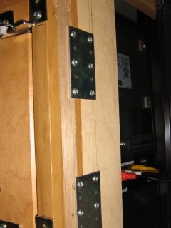
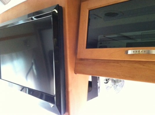
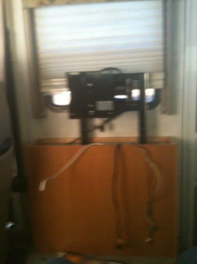
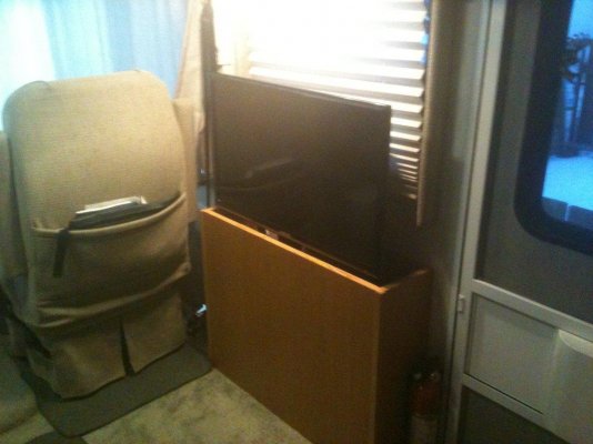
Photo four - Semi complete
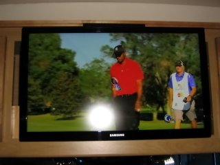
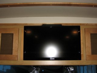
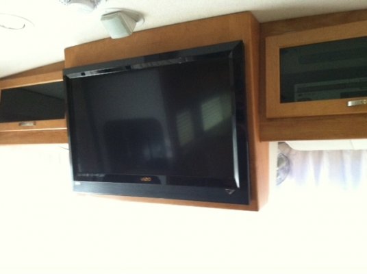
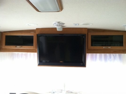
Photo five ? TV installed ? gap around edges
Part four will be the finished ? with trim result.
Michael
")