ac front-rear selector switch

The friendliest place on the web for anyone with an RV or an interest in RVing!
If you have answers, please help by responding to the unanswered posts.
The first thing I would do is disconnect all of the wires that have been tied together in place of the switch.  Then determine which wire goes where.  Finally, with all of those wires separated and no longer connected, reset all breakers and apply shore power to see if everything works.  If everything works properly, remove the shore power and crank up the generator to see if everything works properly.  Finally, go back to shore power and crank up the generator to see if everything including the transfer switch works properly. 

If all of this passes, insert a 3-way switch and you should be back to original configuration.
 
The a/c connects to the centre pole and the two power sources are the end poles.

Are you sure of that.??

It seems to me that the feed should be in the centre and 1 AC is connected on each of the ends. From the OP's description of the wiring diagram, the 20A from the generator seems like it bypasses the ATS going to the switch and is double connected to the rear AC feeder wire at that point.

The 30a powers the whole MH except for the rear a/c, the 20a only powers the rear a/c but by the wiring diagram, runs through the front/rear selector switch.

I think TO , not through, because the switch has been placed in the "Front" position, according to your description, and couldn't power the rear AC that way.

I agree with George, that his suggestion is the only way to proceed.
 
Just found this thread. I have a '94 Adventurer 34RQ with the switch

Sounds like you're missing the switch that allows you to use both a/c's when on 30 amp shore power. The switch has 3 positions.1 will operate the front a/c, the second operates the rear a/c and the third allows them both to run by cycling them on and off after a certain time period like 10 minutes front, then 10 minutes rear.

The switch fills about 1/2 the space over the microwave.

Not near MH now, so I don't know name on the switch. Will look at it this weekend and get back to you. Also couldn't find it listed in parts manual, but don't know where they would have put it.


OOPs, further digging found this:

http://www.winnebagoind.com/diagram/1996/120536.pdf

Not what I have at all... check page 4.


Merrill
 
The a/c connects to the centre pole and the two power sources are the end poles.
Are you sure of that.??

It seems to me that the feed should be in the centre and 1 AC is connected on each of the ends.

You caught me in a major goof, Alfa. Thanks for being on the alert!  I was thinking about the generator/shore switch I had just mentioned and gave the wiring for that rather than the Front/rear switch.  DUH!  Your version of the wiring is correct.

My apologies to everyone - I edited the original to highlight the mistake.
 
I just removed mine recently as it had failed. The original design of the switch was so that when the generator was running both a/c's could operate, when on shore power either or could be ran. If you are triping your breaker the wiring now is not correct. There are 4 wires in the box, front a/c, rear a/c, 20 amp circuit from the breaker panel and 20 amp circuit from the generator. When the switch is on front a/c the circuit from the electrical panel goes to front a/c and the 20 amp circuit from the generator goes to the rear a/c. This allows the generator to run both when on because the front is feed through the transfer switch and electrical panel. The rear is feed straight from the generator. The switch is a cam switch and probably pricey. If whoever removed the switch did not wire it back this way then they may have put the 20 amp circuit from the generator, the electrical panel circuit and both a/c's together thinking they could run both a/c's either way but when there is shore power and the genset is running it will trip the generator breaker (they will both be hot). What the previous owner of my RV did is interupt the generator circuit with a plug so it can be pluged in seperate to run both a/c's when on shore power (1-30 amp, 1-20 amp) or pluged into the generator when on generator power but that realy is a diffrent issue. Hope this helps.
 
Not sure what a 'cam switch' is, perhaps a type of rotary switch, but your explanation makes a lot of sense
 
Thanks, asuperheat. A switch like that solves the questions raised earlier in this thread and the 4th wire explains the feedback problem on shore power. 

I'm having dome difficulty imagining how the switch physically works, but the function makes perfect sense
 
The cam switch is a switch that has a series of cams inside it to make a series of normaly open and normaly closed contacts. Actualy they can be configured for many diffrent setups all normaly open, all normaly closed or a mix of both. I took mine apart and was quite impressed with it. I choose not to replace it because the way I wired it back works good for me, I only need the rear air in the hotest weather and I have a solution for that. Im sure the switch could be replaced but the wires will still have to be identified and the wires will need to be landed on the right terminals or you will need another switch because if you short it out it's toast. The way mine is the circuit from the generator to the cam switch was interupted in the generator compartment, a plug was installed on the end going to the cam switch and is now permatley wired to the rear a/c. The circuit leaving the generator that use to go to the cam switch now has a receptical installed on it. The plug and receptical make the circuit as one when pluged together and is protected by the circuit breaker on the generator. The circuit from the breaker panel is permately wired to the front a/c so when on shore power or generator power it is protcted by the breaker in the electrical panel. When on shore power I unplug the circuit in the generator compartment and plug it into a 12 guage cord and plug it into a 20 amp plug on the shore power and it is protected by the 20 amp breaker at the pole and I can still run both a/c's without issue. I did not wire the plug and receptical it was done by the previous owner and works well. Wiring it this way it never shorts out with the generator and shore power on at the same time, the circuits are always protected and I can run one or both a/c's with very little effort. This is why I did not bther replacing my switch when it failed.
 
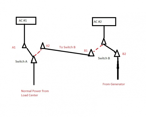
This job can be done with two SPDT (Single Pole - Double Throw) switches, as in the attached crude diagram. Cost should be under $5.

Switch A controls the distribution of the normal 30A/120v power from the RVs load center (breaker panel), whether it comes from shore cord or generator.  This is the Front/Rear switch.

Switch B controls the power line that comes direct from the generator, bypassing the transfer switch and load center. This is the Generator Rear Switch.

With Switch A in the A1 position, it powers the #1 (front) a/c from the load center
With Switch A in the A2 position, it sends normal load center power to one side of Switch B

With Switch B in the B1 position, power from A2 (the load center) flows to AC #2 (rear)
With Switch B in the B2 position, power direct from the generator flows to AC #2 (rear)

When the generator is on, the auto transfer switch send generator power to Switch A via the load center, so AC #1 can be powered either by shore or generator, as needed. AC #2 gets generator power direct via Switch B.

The solid black lines on the switch represent the usual switch position, the red dotted lines are the alternate positions.

Anybody see any problems with this?  I'd hate to screw up his wiring any worse than it now is! The only thing I don't know without seeing it is how the neutrals are arranged. Might need a double pole switch if they have to be switched as well.
 

Attachments

  • Two AC Switching.jpg
    Two AC Switching.jpg
    70.5 KB · Views: 28
The only problem is if you use regular Single Pole Double Throw (SPDT) switches, the neutral is unswitched and remains connected between shore power and the generator.

It's not really a problem in normal usage, but can be if the shore power socket has reversed hot and neutral leads.  The generator's neutral would then be energized by the miswired shore power hot line.  Again, not necessarily a problem if the generator has an isolated neutral,  but if the generator neutral is bonded to chassis ground you'll energize the chassis.

I like the idea of isolating the rear air conditioner wiring and running it to a plug that can be either plugged into a socket connected to the 20 amp output of the generator or to it's own extension cord running to shore power.  Simple and there's no way to cross-connect the generator to shore power.
 
The only problem is if you use regular Single Pole Double Throw (SPDT) switches, the neutral is unswitched and remains connected between shore power and the generator.
That was my concern too, Lou.  Need to look at  the original wiring to see if there was a separate neutral for the direct-to-generator circuit. The OP didn't mention one, but he may not have known to look for it either.

Note, however, that when the generator is running, the load center is also using the generator neutral and there is no connection to shore neutral (the Auto Transfer switch assures this). You can't have both at the same time, for obvious reasons.

 
On mine the nutrals were switched also, I think this is why they used the original switch they did it was one switch kinda like these but a diffrent manufactuer https://www.c3controls.com/cam-switches.cfm I guess you could just get another cam switch. Mine was a CA20 I don't remember the manufactuer but I think it is still at my office. There was a series of jumpers to get the switch to do what they wanted originaly.
 
Actualy with a little surffing I think the original switch in mine was a kraus & naimer CA20 A222-600. It shows this as a 1-2 switch and it is 3 poles like mine was, 60 degrees like mine also. Not positive but almost sure thats the original switch in mine.
 
Or take two regular 3-way wall switches.  Wire one on the hot side of the circuit, the other on the neutral, and fabricate a handle to connect them so they can ONLY be switched together.

Sounds kludgy, but if done right will solve the neutral problem.
 
Double pole, double throw switches aren't that hard to find.  Just be sure they're break before make or there could be fireworks :)
 
I have a 94 winnebago sun cruiser with the same issue but mine still have the pulse air model# a/c 1157 aftermarket installed, mine alternates running the front and back a/c while plugged on 30 amp shore power. Front one runs for about 12 minutes then switches to back running for 8 minutes.
I changed mine like 5 years ago, it went bad again but now I can not find a new unit anywhere. Just like previous unit it won't switch between a/cs. Anybody knows where could I find it or an equivalent to it?
Im sure this will take care of your problem as well.
 
Welcome. Find an electronics geek, amateur radio operator, etc and present the situation to them. I don't think this would be too difficult to design using a microcontroller, couple of relays and a few miscellaneous components. This would be a way fun project to tackle - I wouldn't mind trying it but we leave in a few days for the summer.
 
Back
Top Bottom