OP
OP
Kim (skyking4ar2) Bertram
Moderator Emeritus
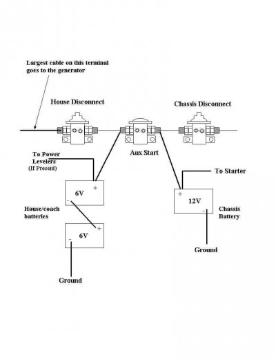
I still have the issue with the generator not starting, no clicks, no nothing, like a relay or something being open.
I really cannot see where that circuit starts and what might be in that circuit, including something on the transfer switch board, that might have gone out.
Any general thoughts on where to start testing?
I really cannot see where that circuit starts and what might be in that circuit, including something on the transfer switch board, that might have gone out.
Any general thoughts on where to start testing?