Rubi's Rear Axle Improvement Initiative (RRAII)

The friendliest place on the web for anyone with an RV or an interest in RVing!
If you have answers, please help by responding to the unanswered posts.

John Canfield

Site Team
Joined
Aug 8, 2006
Posts
14,121
Location
Texas Hill Country
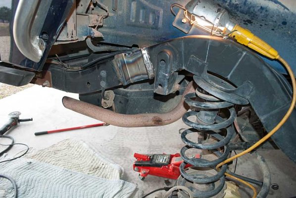
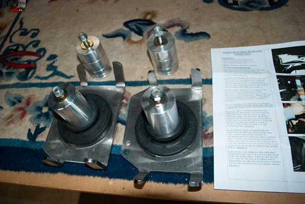
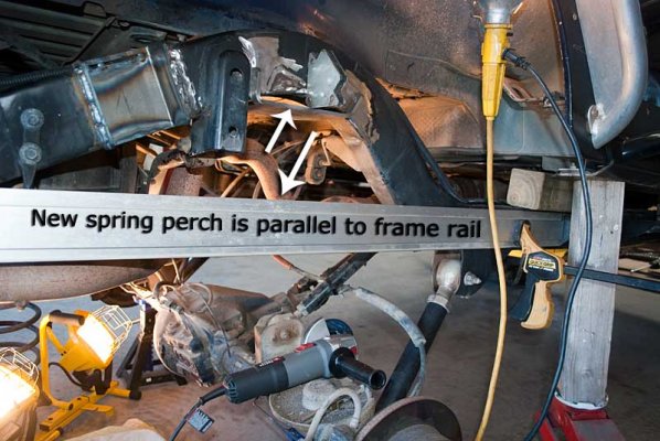
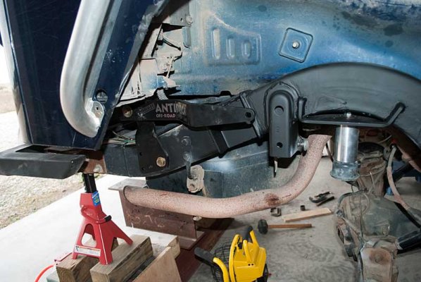
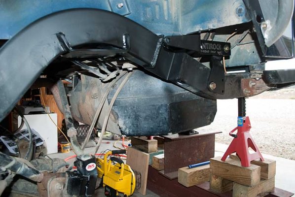
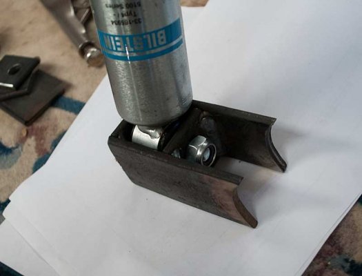
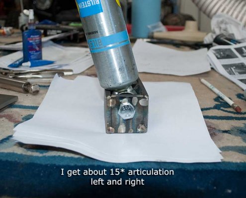
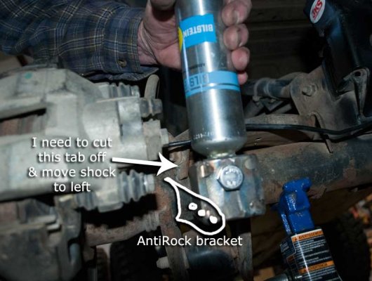
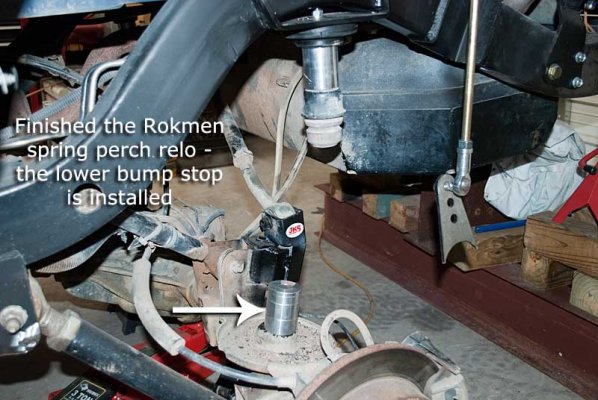
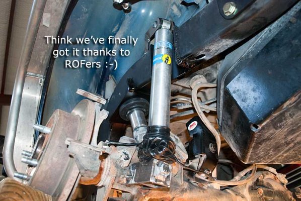
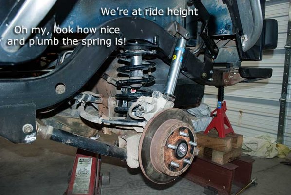
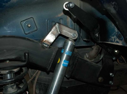
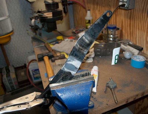
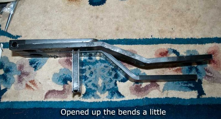
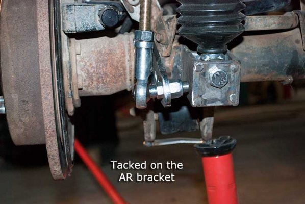
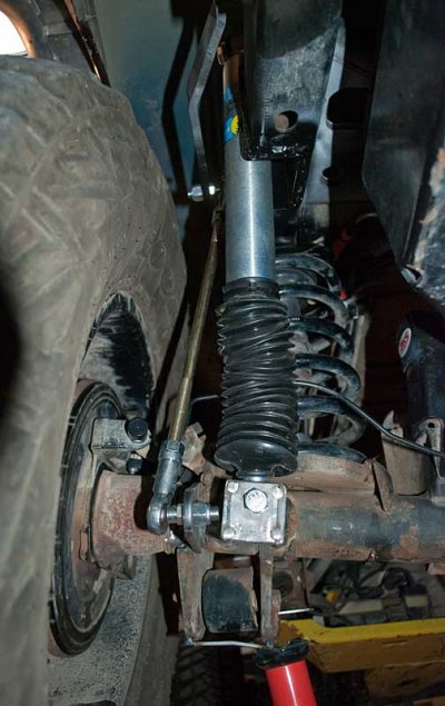
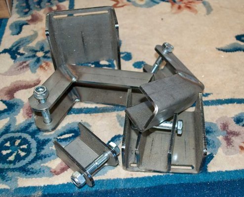
I'm copying my thread over from the Rubicon forum.  What I've done to the rear axle is outboard the rear shocks (I ripped one out in Arizona), moved the upper rear spring perch aft to make it more perpendicular to the axle and installed a Currie rear AntiRock in place of the factory sway bar. Also I installed bump stops to prevent breaking the new Bilstein shocks.

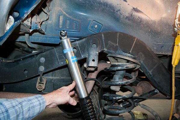
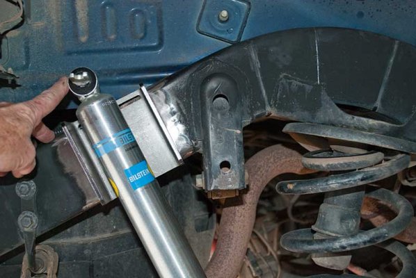
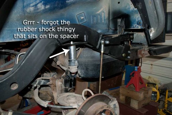
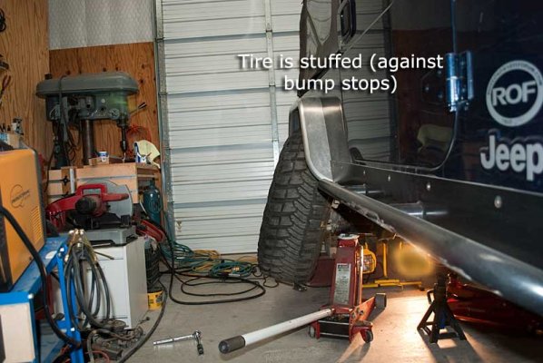
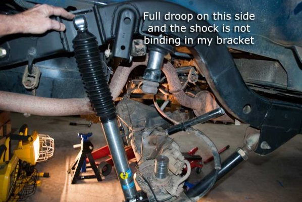
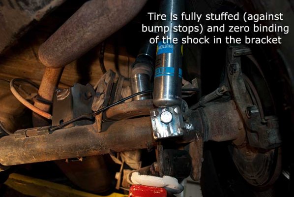
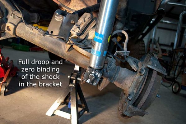
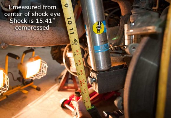
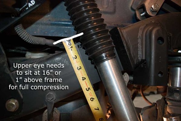
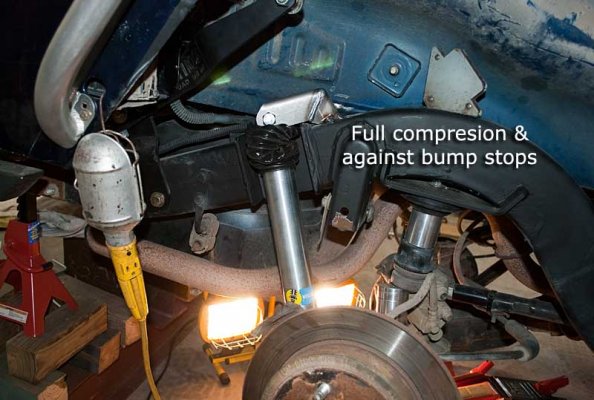
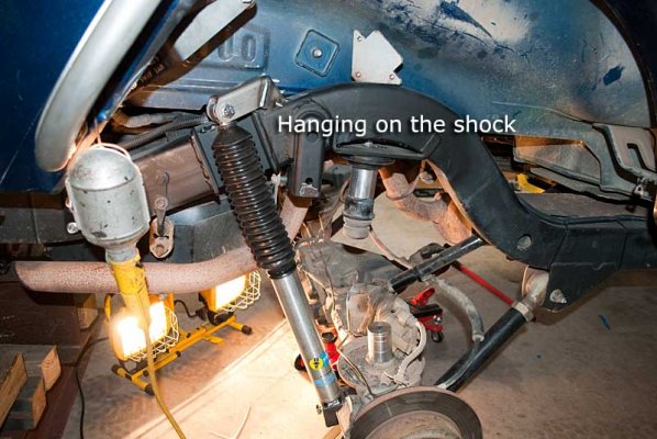
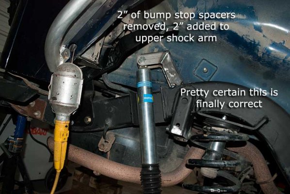
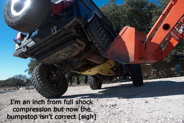
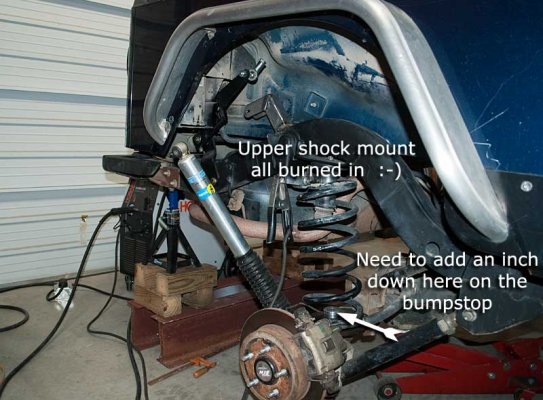
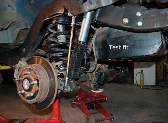
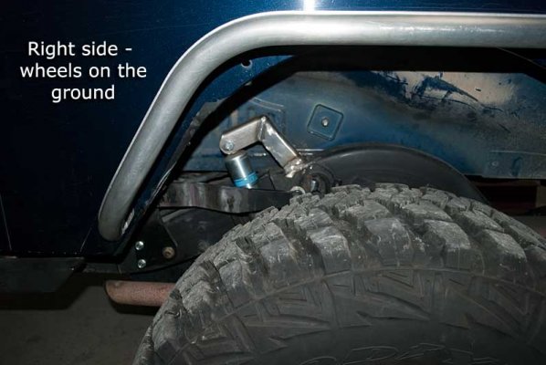
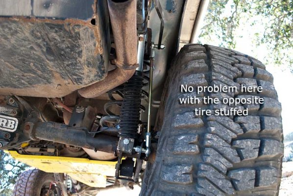
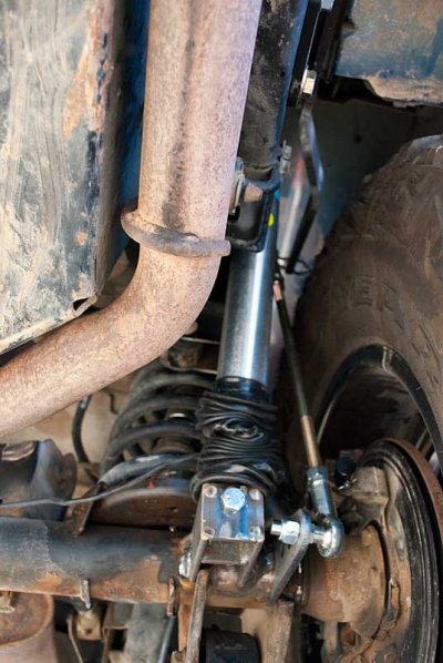
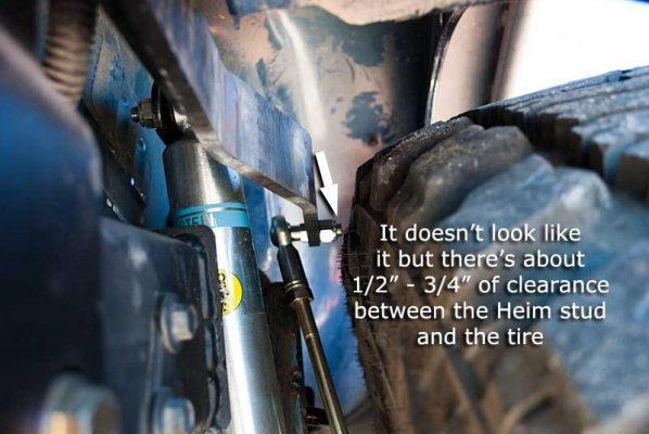
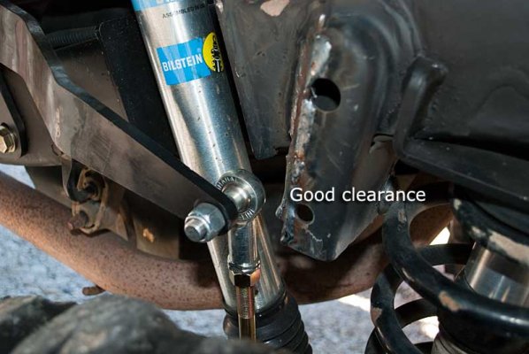
The Bilsteins have about 10" of total travel so it is critically important to set the bump stops (and the Clayton outboard shock tower height) to where there is about 5" of travel up and down from ride height.  The bump stops prevent compressing the shocks too much and ruining them or breaking a mount (or stuffing a tire into a fender or wheel well opening.)  It took a bunch to time to get this set up but the time was well invested, we've wheeled some tough trails and all is good.

------------- Let's get started ------------------

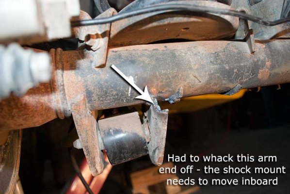
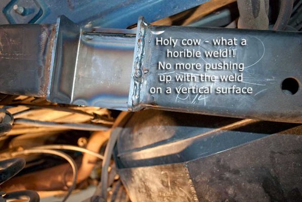
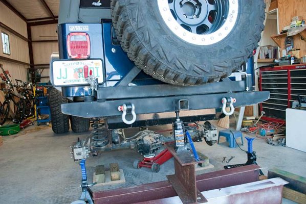
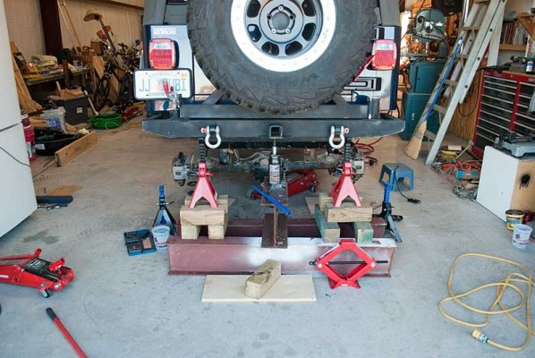
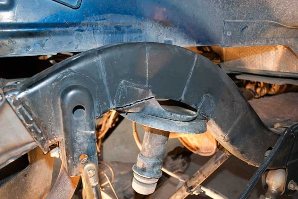
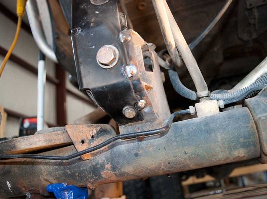
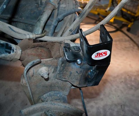
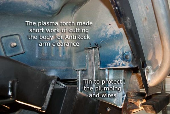
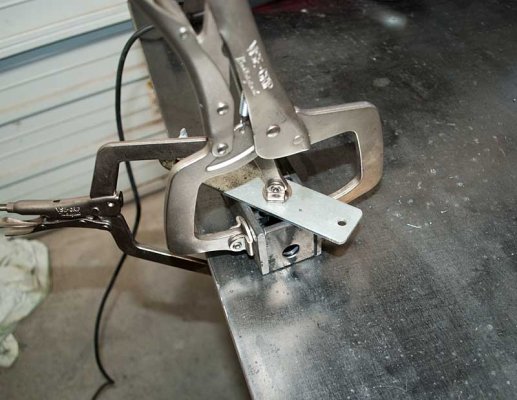
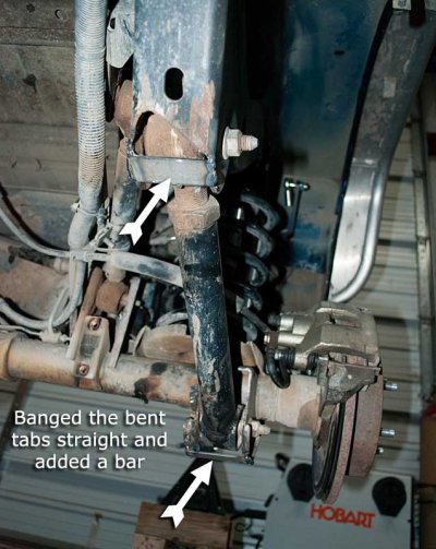
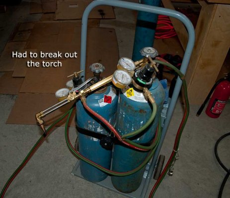
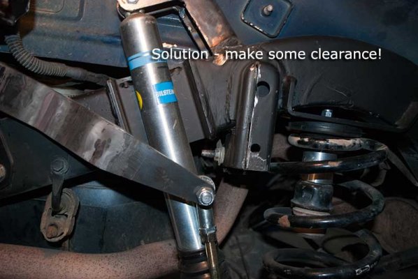
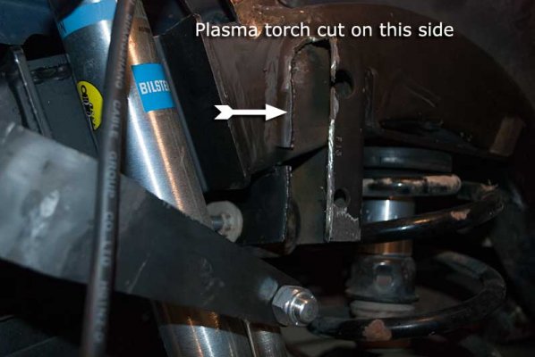
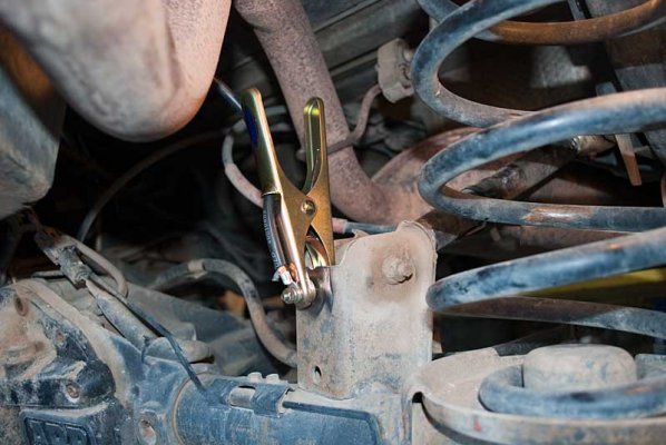
While not having anything to do with the rear axle, I replaced my front shocks to get that out of the way. Then I jacked up the the right rear, removed the tire, removed the shock (I discovered the shock shaft was slightly bent ), removed the sway bar on that side, removed the JKS shock extenders, and then used the plasma torch to cut off the shock mount from the axle.

Note to self: buy one of those funky welder head scarfs/cap/whatever they call it - I just hate the smell of burning hair :? . Also discovered it's easy to cut (or weld) while standing up with the work on my welding table but it's quite another thing to cut laying on your side trying to work around various obstacles. Then my air compressor pressure switch didn't cut on (the switch is having problems) and all of a sudden the plasma torch wasn't working right due to low air pressure. DOH!

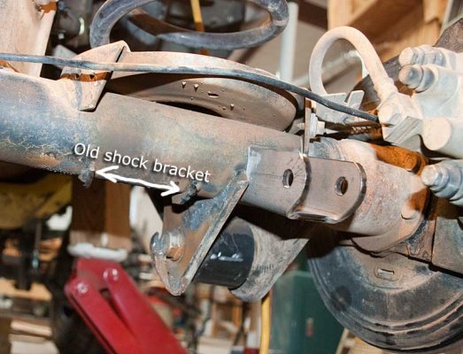
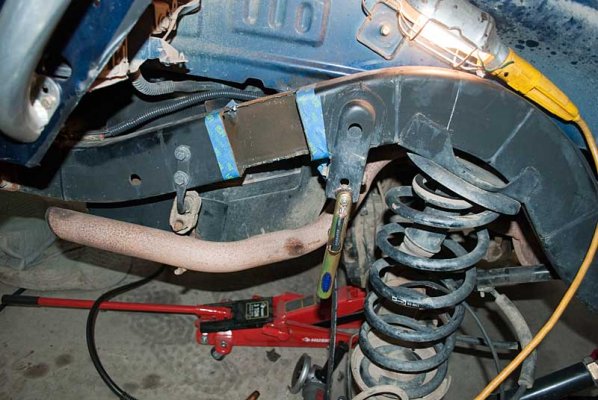
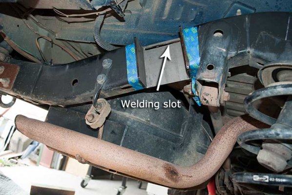
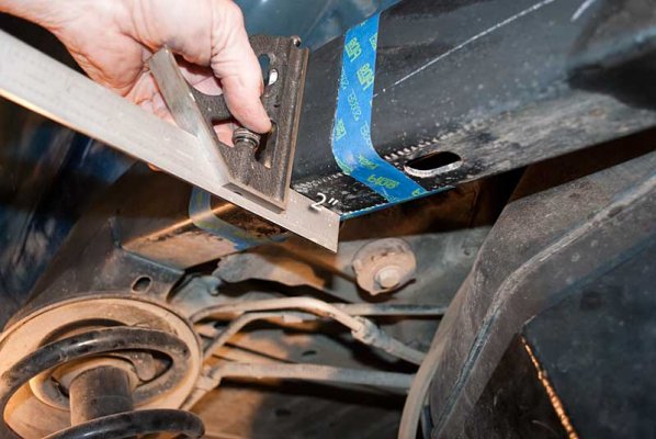
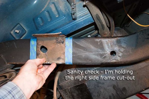
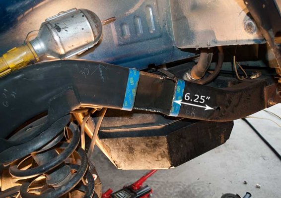
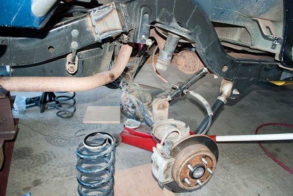
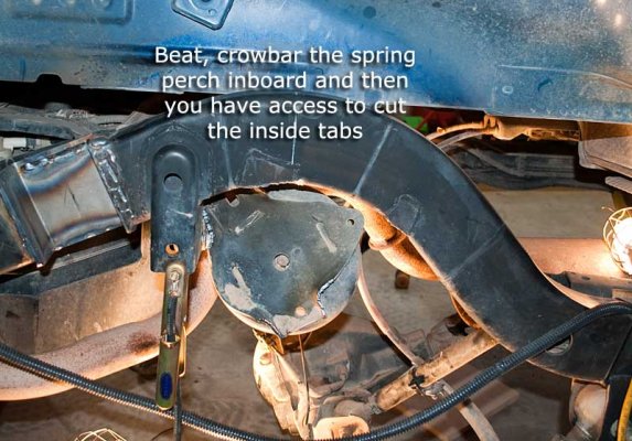
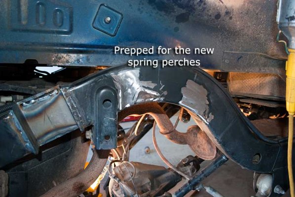
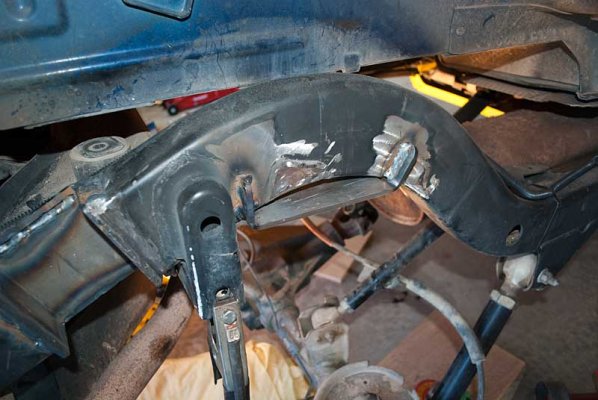
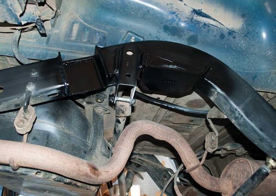
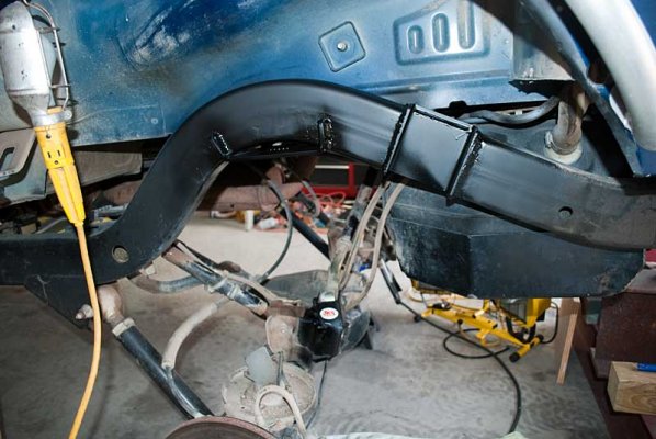
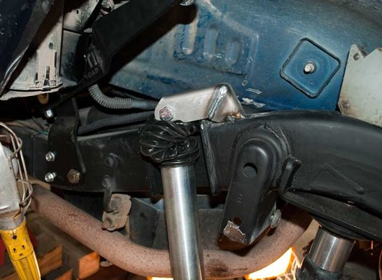
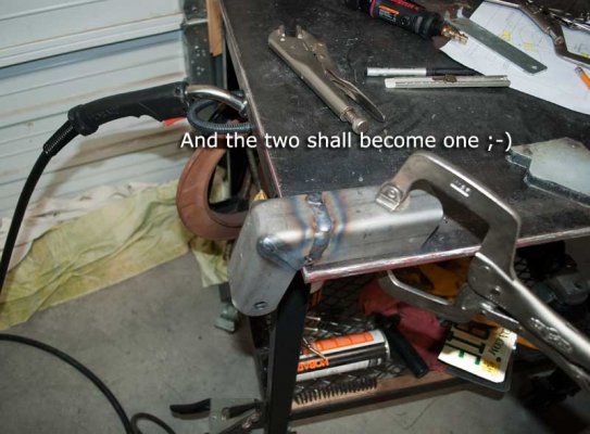
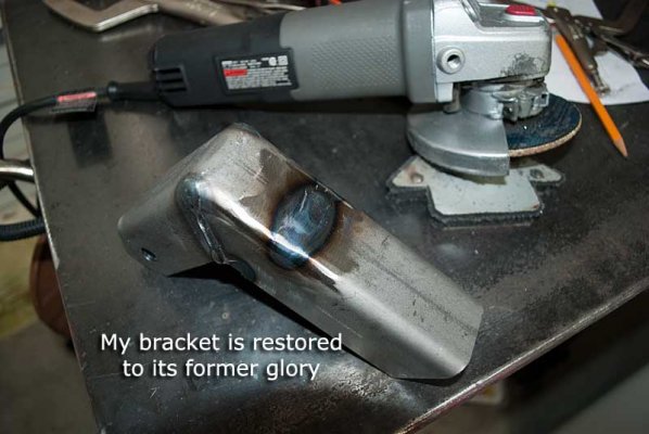
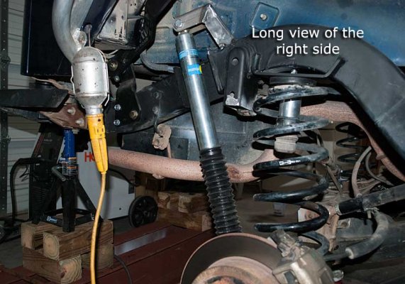
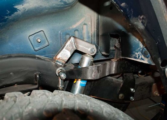
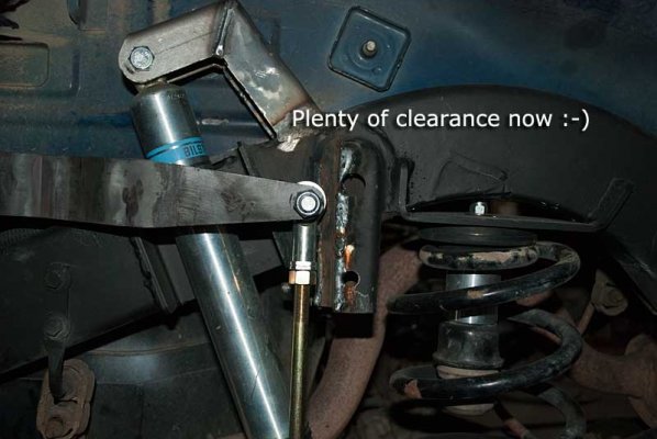
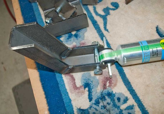
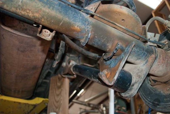
Finally got the shock bracket cut off and ready for some grinding tomorrow (for aesthetics - the new bracket will be welded in another area of the axle.) While I have everything up and exposed on the right-rear, I might as well cut the frame for the Clayton outboard shock bracket (they have a drawing showing exactly where the bracket is to be frenched in) and weld that in.

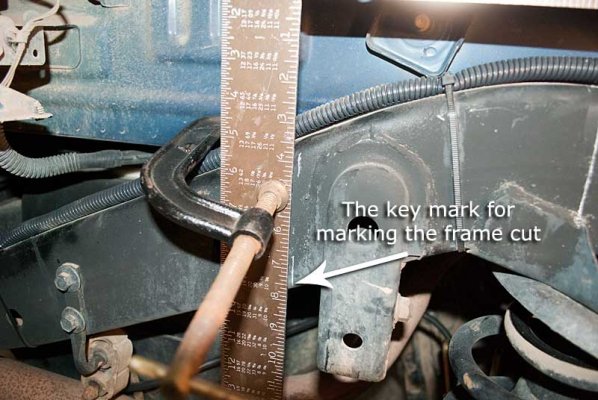
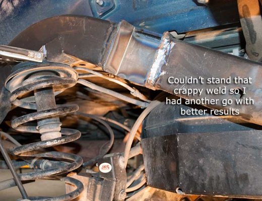
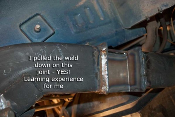
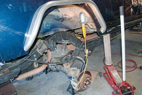
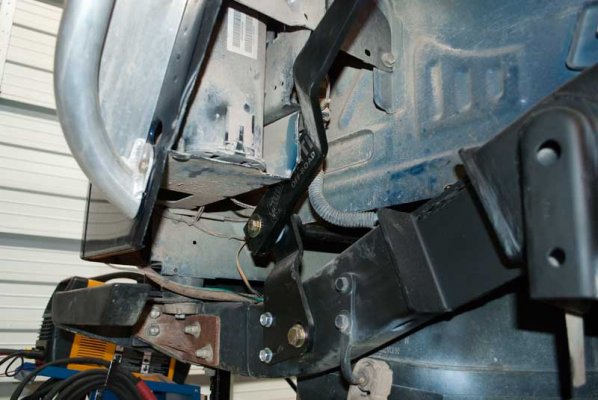
I'll tack in the new shock mount on that side, again there is a Clayton drawing showing exactly where the bracket goes but tacking it first is a great idea.

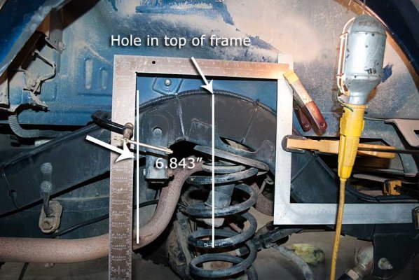
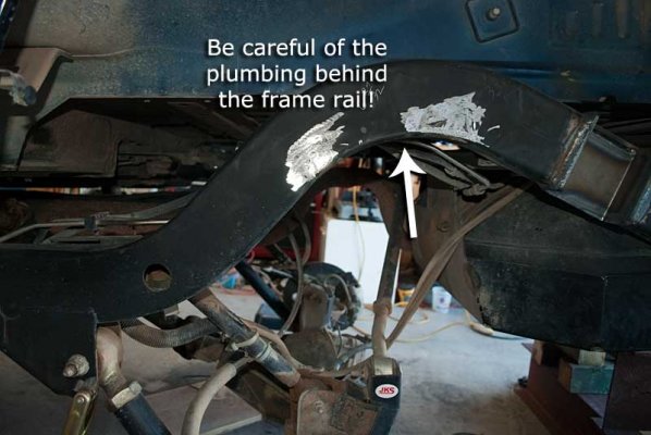
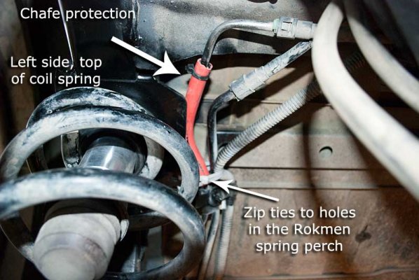
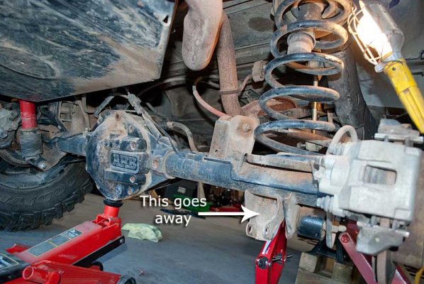
Errata: It looks like the brake line will be in the way of the new shock bracket - Hmmm.
 

Attachments

  • ClaytonParts.jpg
    ClaytonParts.jpg
    65.4 KB · Views: 21
  • Clayton1.jpg
    Clayton1.jpg
    48.3 KB · Views: 19
  • ClaytonShockAxleTubeMount.jpg
    ClaytonShockAxleTubeMount.jpg
    70.5 KB · Views: 21
  • BentRod.jpg
    BentRod.jpg
    22.7 KB · Views: 20
  • GoodGround.jpg
    GoodGround.jpg
    49.6 KB · Views: 19
  • OriginalShockBracket.jpg
    OriginalShockBracket.jpg
    68.3 KB · Views: 19
  • ShockBracketCutOff.jpg
    ShockBracketCutOff.jpg
    44.4 KB · Views: 20
Today was slice and dice (and weld) day.

Objectives were to tack the new lower shock mount in place and cut the frame for the U-shaped channel and weld it in place on the right side.

I ground down the old shock mounts on the axle tube somewhat, I thought this was a whole bunch of work for very little payback since there was no reason other than cosmetics, so taking the path of least resistance, I quit after three or four minutes of grinding (grinding standing up is okay, laying on your side and grinding isn't a lot of fun at my age.)

After a couple of no-goes, I got the new shock bracket tacked on the axle tube. Welding in confined and constricted places is a bit of a challenge I quickly discovered. Then it was time to move on to the really big deal - cutting the frame for the U-shaped bracket that will form the trough for clearance for the outboard shock.

I spent quite a bit of time measuring for the frame cut (and worrying about) - as a huge time saver Clayton has a drawing detailing exactly where the frame needs to be cut however the problem is trying to figure out how to measure the offset from the hole in the top of the frame arch (that's over the axle) and project that measurement to the key point on the frame for the U-shaped bracket (the forward lower point on the frame - it will make more sense with the attached pictures.)

After using two squares, a small square to square up the overlapping two large squares and a few clamps I felt comfortable with making the key mark on the frame to then place the U-shaped channel on the frame and mark the frame cut lines (refer to the picture.) Wanting a further sanity check, I took a shock and mounted it on the lower mount and looked to see where it crossed the marks on the frame - I was okay with that check so it was time to slice and dice :) .

After marking the frame I went to work with a cut-off wheel on the 4.5" grinder and made all of the cuts possible with it, then switched to an air tool with a small diameter cut-off wheel and then finally the plasma torch to finish up the cuts. Cutting the bottom of the frame was a bit of a hassle.

Amazingly I got very close to a great fit for the U-shaped bracket - only had a too-large gap in one short area that some extra wire from the welder cured. Had to do a little grinding in one small area but I'm really pleased the cut went so well.

Fitted the U-shaped bracket into the frame void and welded it up. I don't like welding vertically ('cause I'm a newbie welder) but I chose to push the weld (go vertical) up and that worked okay. Welding the bottom was an exercise in getting me and the gun into the correct position. The welds aren't pretty but I got good penetration (nice heat signature on the U-shaped bracket) and I'm 100% confident they are nominal.

That was the extent of the work on that side for the moment so time to get the tire mounted, get it on the ground and move to the left rear. Got that side up in the air, removed the tire, shock and I fully removed the sway bar (partially discoed at this point) and then it was cocktail time  :D.

Tomorrow I think I'm taking the Bushmaster .308 to the range and working a bit on the left side of the Jeep (retirement is a beautiful thing.) The Rokmen spring perch relo kit arrived today so the plan is to finish the left side (like I did for the right side) and then dive into relocating the upper spring perches.
 

Attachments

  • NewShockBracketTackedIn.jpg
    NewShockBracketTackedIn.jpg
    63.5 KB · Views: 15
  • MeasuringForFrameCut.jpg
    MeasuringForFrameCut.jpg
    65.4 KB · Views: 15
  • SanityCheck.jpg
    SanityCheck.jpg
    59.3 KB · Views: 13
  • KeyMarkForFrameCut.jpg
    KeyMarkForFrameCut.jpg
    62.2 KB · Views: 13
  • FrameCut.jpg
    FrameCut.jpg
    64.4 KB · Views: 13
  • BracketTestFit.jpg
    BracketTestFit.jpg
    59.2 KB · Views: 13
  • GoodFit.jpg
    GoodFit.jpg
    49.5 KB · Views: 15
  • WeldedIn.jpg
    WeldedIn.jpg
    63.2 KB · Views: 15
Not a whole bunch of progress today, I was working on the left rear for only about three hours this afternoon. I needed to assemble a 50A/220V extension cord to get the plasma torch and Mig welder over to the left side of Rubi so after $80 worth of parts acquired before lunch and a few minutes of assembly, I had the mother of all extension cords ready. I also picked up a very small air powered right-angle die grinder with some appropriately sized sanding discs for welding prep in those tight areas (dang, hated to buy another tool  :) .)

After practicing on the right side yesterday, I quickly got the left side shock mount cut off the axle tube thanks to the plasma torch (ooh - I'm liking this guy!!!) I had a measurement for the new shock brackets (outside to outside) from the Clayton drawing and measured from the previously tacked-in right-side shock mount to the left side and it was not good. The right side shock mount was positioned too far to the end of the axle tube so I'm going to grind out that tack weld and start over. Part of the problem was interference from the OEM lower control arm mount, but I discovered I could easily cut off the interfering part of that bracket so I can reposition the shock mount.

Got the frame cut for the Clayton U-shaped bracket using the cut-off wheel and the plasma torch. It's going to take just a couple of minutes of grinding to get the bracket nestled in and ready for welding.

It became obvious today I need to concurrently install the rear AntiRock and the new axle shock mounts - the AntiRock arm and the shock arm need to coexist in very close quarters on the tube so I need to accommodate and plan for both at the same time.

Next step is to weld in the left side U-shape channel in the frame cutout and then move the spring perches (which arrived a couple of days ago.) After that I can work on the AntiRock and the axle shock mounts.
 

Attachments

  • ControlArmCut.jpg
    ControlArmCut.jpg
    51.3 KB · Views: 12
  • InsideFrameCutLine.jpg
    InsideFrameCutLine.jpg
    48.5 KB · Views: 12
  • SanityCheck.jpg
    SanityCheck.jpg
    51 KB · Views: 14
  • LeftSideFrameCut.jpg
    LeftSideFrameCut.jpg
    54.9 KB · Views: 11
  • RokmenSpringPerchRelo.jpg
    RokmenSpringPerchRelo.jpg
    50 KB · Views: 14
Back at it after a weekend off (us retired guys also take weekends off - sometimes.) I got the left side shock U-channel welded into the frame and I had one of those "oh crap" moments (it's been building up for a while) when my push vertical weld turned out to look like crap (see pix) much like the other side only worse.

For the non-welders reading this, a push weld (wait for it - this is complicated) is where you push the electrode or MIG gun away from you, a pull weld is.. okay, you get the idea. On a flat surface I always like to push a weld because the arc lights up the joint ahead and it's easy to stay on-course.

I discovered today to NOT push a weld uphill, pulling it down worked really, really well though. I'm still learning. I was so horrified at the crappy push weld I had to grind it out and do a pull weld downhill. After looking at the right side U-bracket welds I'm going to grind out the vertical welds and redo them - I hate crappy looking welds.

Next mission was to remove the springs and then cut out the old spring perches. It took some critical thinking to figure out how to jack this and that up to where I had a safe work environment (safety is job #1) to where I could remove the springs. I discovered it was necessary to disconnect one end of the trackbar to let the axle fully droop (the frame was previously jacked up) to where I could easily pull the springs out - I was wondering about that. With the trackbar in place, one side can droop a bunch more than the other. One of these days the JKS track bar will be for sale.

It supposedly makes the job of cutting out the OEM spring perches easier if you jack the body up a few inches, so that's what I did. A little earlier I had loosened (loosened not removed) several body mount bolts and removed the four bolts in the rear and then discovered it was helpful to remove the three side body mount bolts as well to get the body up as much as possible on that side.

Then it was cocktail hour (actually time to feed the ranch animals first, then cocktail hour  :D .) Tomorrow is plasma torch time - we're whacking spring perches.
 

Attachments

  • YukWeld.jpg
    YukWeld.jpg
    51.5 KB · Views: 13
  • WeldRework.jpg
    WeldRework.jpg
    68.3 KB · Views: 13
  • BetterWeld.jpg
    BetterWeld.jpg
    37.1 KB · Views: 12
  • DroppingAxleRemoveSprings.jpg
    DroppingAxleRemoveSprings.jpg
    69.1 KB · Views: 14
  • FrameUP.jpg
    FrameUP.jpg
    67.6 KB · Views: 12
  • SpringOut.jpg
    SpringOut.jpg
    64.3 KB · Views: 12
  • ReadyToCutSpringPerch.jpg
    ReadyToCutSpringPerch.jpg
    64.3 KB · Views: 12
Good work day today. Got the right side spring perch cut out - the plasma torch is an amazing tool and made quick work of cutting the perch out. Easiest way I decided is to cut the outboard perch tabs then whack (or crowbar) on the perch to bend it inwards to where you expose the inner tabs. Then you have easy access to cut the inner mounting tabs. Oh, it is almost a necessity to jack the body up as much as possible to gain access to the inside of the frame rail. I loosened all of the body bolts, removed the rear four bolts, then removed the three on the side I was working on. The tub will raise up quite a distance giving necessary clearance.

It's really not necessary to grind out the OEM perch welds on the frame rail but it looks a whole bunch nicer on the outside of the frame if you do. I got the Rokmen perch positioned and tacked it on the outside, then moved to the inside to get that difficult weld out of the way. There is fair access to the forward inside mounting tab, but completely lousy access to the inside rear tab. The best I could do for that tab was about 1/2" of weld on the forward side, but that should be plenty to hold the perch in position.

Got that all welded up, cleaned with solvent, primed, then topcoated. It looks pretty good painted up. Then I was able to move the circus to the other side of the axle and I had time to cut that perch off and grind out the outboard welds. No time to go further with the spring perch effort so I got busy installing the new shock eye bushings in place of the pin bar tab. That went faster than I imagined so the shocks are ready to mount, unfortunately I'm not sure where I'm going with shock mounts.

At this point, I'm seriously thinking about fabbing up my own mounts - the plasma torch has provided a new dimension to metal working.

Tomorrow's plan of the day is to finish with the left side Rokmen perch install and then I think I'll get busy with the rear AntiRock since the new shock mounts have to peacefully coexist with the AntiRock link that welds on to the axle tube. Things are a little fuzzy here, but I don't think I can set the spring bump stops until I get the lower shock mounting brackets on the axle.
 

Attachments

  • OutboardSpringPerchCut.jpg
    OutboardSpringPerchCut.jpg
    56.3 KB · Views: 10
  • CutInboardTabs.jpg
    CutInboardTabs.jpg
    70.9 KB · Views: 10
  • Prepped.jpg
    Prepped.jpg
    57.9 KB · Views: 10
  • PositioningNewPerch.jpg
    PositioningNewPerch.jpg
    67.6 KB · Views: 9
  • NewSpringPerch.jpg
    NewSpringPerch.jpg
    51.3 KB · Views: 12
  • PaintedUp.jpg
    PaintedUp.jpg
    65.2 KB · Views: 11
  • LeftSidePerchCutOut.jpg
    LeftSidePerchCutOut.jpg
    45.2 KB · Views: 12
Yet another good work day (except my knees started to hurt about 3PM.) I've got a good amp, powered woofer, and speakers in the shop so Pandora Radio was blasting out my Bob Marley channel since I was getting tired of Pat Benatar and similar genera.

I finished up with the Rokman spring perch install on the left side. This one went much faster than the right side due to a) experience and b) there's a little more room to work with on the left side (as I recall) assuming you disconnect the track bar (which is highly recommended.) I was a very happy camper when finished with the spring perch install.

In the process of disconnecting the axle end of the track bar I discovered the JKS trackbar bracket I installed a couple of years ago was way loose :eek: - no telling how long the trackbar has been slamming the JKS bracket around. This is a little disappointing since the nuts on the bracket were locknuts, however the problem is (should be) permanently solved since I tack welded the bracket in several places, yea!

There was time to get started on the rear AntiRock which had its frustrating moments - I spent some time beating on the sway bar rod this way or that way and then the nylon bushing in the frame bracket would move out. It took some creative mechanical skills (C-clamps, big frigging hammer, etc) to get the thing settled down and in its proper place.

Now I need to move on to that dreaded task of the axle shock bracket. I think I have a good plan for a fabbed up shock bracket, so I'm going to work on that tomorrow.

Wow, this stuff is fun!
 

Attachments

  • LooseTrackbarBracket.jpg
    LooseTrackbarBracket.jpg
    57.7 KB · Views: 11
  • BracketTackedBottom.jpg
    BracketTackedBottom.jpg
    55.8 KB · Views: 11
  • BracketTackedSide.jpg
    BracketTackedSide.jpg
    52.4 KB · Views: 10
  • LeftSidePerchFinished.jpg
    LeftSidePerchFinished.jpg
    55.9 KB · Views: 10
  • AntiRockRightSide.jpg
    AntiRockRightSide.jpg
    57 KB · Views: 10
  • AntiRockLeftSide.jpg
    AntiRockLeftSide.jpg
    59.7 KB · Views: 11
Time for another Pandora station change this morning - I was in the mood for some Blues so B.B. King was on (saw him a few years ago in a concert.) You have to love Pandora.

The plan of the day was to go as far as possible with the AntiRock install and then start planning (and worrying :) ) about the axle brackets for the shocks and AntiRock.

There is a little tub inner sheet metal to be cut for clearance of the AntiRock arms and the plasma torch saved the day yet again. I was working on the left side trying to cut the sheet metal with my little air cutoff tool, then tin snips and then I decided this was crazy and Mr. Plasma came out. YES! Short work was made of the necessary cuts. What a great tool to own.

Then it was time to move on to thinking about the shock and AntiRock bracket install on the axle tube. After looking at the situation, it became quickly obvious that I really do need to flip the brake caliper to free up clearance on the aft end of the axle :? . Without a caliper flip, it would be really, really tricky to get a vertical (as in plumb) line from the AntiRock arm to the AntiRock bracket on the axle tube.

Tomorrow I'll make a prototype shock bracket for the axle and I think I'll get started on the Swag body mounts since I'll be in a holding pattern for any further axle progress until I can do the caliper flip.
 

Attachments

  • AntiRockClearanceCutLeftSide.jpg
    AntiRockClearanceCutLeftSide.jpg
    52.2 KB · Views: 9
  • AntiRockClearanceCutRightSide.jpg
    AntiRockClearanceCutRightSide.jpg
    44.7 KB · Views: 9
  • MIArubberCollar.jpg
    MIArubberCollar.jpg
    51.2 KB · Views: 9
  • NeedToFlipCalipersSideView.jpg
    NeedToFlipCalipersSideView.jpg
    65.2 KB · Views: 9
  • NeedToFlipCalipers.jpg
    NeedToFlipCalipers.jpg
    33.3 KB · Views: 9
Yet another music genre change made on my Pandora today - The Chieftains were on center stage.

First thing this morning I installed the rubber spring thingys (forgotten yesterday) that sit on the Rokmen spring perch relo kit spacers.

Since I already had one of the Clayton shock axle brackets tacked on the axle tube, I thought it would be interesting to put a shock in the bracket and jack up that end of the axle to see for myself what all of the fuss was about with that kind of bracket (shock eye parallel to axle tube.)

There was no significant binding of the shock (in the Clayton bracket) until the tire would have been approaching being fully stuffed into the wheel well. I'd say binding of the shock would happen with 2-4" of shock travel left ::) , so, it was time to fab up some custom brackets (as I expected - thanks to Mouse for pointing me in the right direction!)

It was extremely time consuming designing and fabbing up the brackets, and I don't even know if they are going to work. I used flat bar 1/4" thick and 2" wide since I had a stick laying around in the shop, but maybe 3/16" would have been okay.

The plasma torch was amazing - I was able to cut the arch on the bracket where it sits on the axle tube in a minute or so, without the torch I would have been using a cut-off wheel and grinder (forever.)

I had a bunch of spatter when I welded up one of the brackets - time to clean the MIG nozzle.

Not sure what I'm going to do tomorrow on Rubi - maybe get started on the Bertha body mounts until the rear emergency brake relo kit arrives (shipped today) and then I can flip the calipers, etc.
 

Attachments

  • ShockBracketFabUp.jpg
    ShockBracketFabUp.jpg
    18.6 KB · Views: 6
  • BottomView.jpg
    BottomView.jpg
    23.7 KB · Views: 8
  • ReadyForTackWelds.jpg
    ReadyForTackWelds.jpg
    51.8 KB · Views: 6
  • ShockBracketTopView.jpg
    ShockBracketTopView.jpg
    25.4 KB · Views: 6
  • 15degreeArticulation.jpg
    15degreeArticulation.jpg
    44.1 KB · Views: 6
  • AxlePlanning.jpg
    AxlePlanning.jpg
    47.3 KB · Views: 7
I'm trying to decide if I had good day today ???.

One minor accomplishment was to install the lower spring perch bump stops which required that I mount a tire and jack that side up as far as I wanted the tire to be stuffed. After I stuffed the right and left sides I realized there was no way the prior bump stops would have met anywhere near the middle of the perches. Even with the new upper perches, the bump stops aren't lined up with a tire stuffed but close enough to work (and work a lot better than the prior setup.)

Then I mounted a shock to the Clayton bracket previously tacked on the right side of the axle tube and jacked up that side to the bump stops - as I tested earlier, there is considerable binding of the shock so the Clayton brackets are definitely not going to be used (I was toying with trying to use them.)

Sometime in this testing process with a tire stuffed in the wheel well, I was looking at clearance with the AntiRock link held into the approximate position of where the axle bracket would be welded and it was not looking good - there was big-time interference between the link and the inside top of the tire  :mad:.

Grrrrr.

There is no way the AntiRock in its current configuration is going to work for me - surprise, surprise, surprise. For a while I thought I installed the arms backwards (surely it's an install problem!!) but after double checking, I don't think so. So I'm thinking I have four choices here:

1 - use wheel spacers in the rear (not going to happen)
2 - sell the AntiRock
3 - try a straight arm instead of the present one with a dog-leg bend
4 - combine a straight arm with moving the AntiRock to the front of the axle

It seems the best option is to call Currie after Christmas and kick it around with them, but after looking at clearances, I don't know why a straight arm wouldn't work - it would move the link inboard far enough to clear the tire. In fact, I'm not sure why the arm has a dog-leg bend in it in the first place but maybe I'm missing something here.

Then I removed the previously tacked in Clayton shock bracket (thank you Mr. Plasma Torch) and tacked in my new shock bracket. It looked promising when I was holding it in position with the axle up and stuffed and at full droop, so I thought let's just see what happens with it tacked in and a shock on it.

Yea - it seems to be perfect! There was absolutely no binding at either full droop or full stuff and there was still quite a bit of shock movement left at both extremes and in both axis (left-right and fore-aft.).

Now I need to figure out how much to cut off the Clayton upper shock mount for my 10" of shock travel, weld those to the top of the frame rail and determine if I need a strap to limit the droop of the axle.

I'll probably not work on Rubi until Dec 26 or later, so no more updates until next week sometime.
 

Attachments

  • LowerBumpStopsInstalled.jpg
    LowerBumpStopsInstalled.jpg
    65.2 KB · Views: 5
  • AntiRockLinkInterference.jpg
    AntiRockLinkInterference.jpg
    40.5 KB · Views: 5
  • SideView.jpg
    SideView.jpg
    59.1 KB · Views: 4
  • RightSideDroopOkay.jpg
    RightSideDroopOkay.jpg
    57.2 KB · Views: 4
  • RightTireStuffed.jpg
    RightTireStuffed.jpg
    48.6 KB · Views: 3
  • RightSideDroopRearView.jpg
    RightSideDroopRearView.jpg
    54.1 KB · Views: 5
Not a lot of progress today. The shop was pretty cold (high 30s) so it took a while to get it up to a comfortable temperature. One major accomplishment was figuring out how tall the upper shock mount needed to be - I measured many times, thought about it, measured again.

I tacked it in place and discovered I had a bind so I ground out the one tack, bolted the shock in the bracket, and did a test fit (what I should have done the first time.) Had to do a little grinding on one edge of the bracket but I got a really good fit. I lifted the axle end up to full compression (against bump stop) and we're golden as far as the shock and where the tire would be in the fender well (I measured 17 1/2" from the center of the wheel to where I've rubbed the fender lip previously.)

Satisfied (until somebody points out a flaw in my logic  ;) ) with the passenger side shock, I moved over to the driver's side and tacked the shock bracket on the axle. After bolting the shock on the bracket, I discovered I need to grind out the tacks and rotate the bracket down slightly [sigh.]

I think the current plan is to finish with tacking in the driver's side shock brackets, do the caliper flip, put the tires back on and use the tractor bucket to exercise the suspension to make sure we're okay. Then I can tackle the rear AntiRock.
 

Attachments

  • MeasuingFromBottom.jpg
    MeasuingFromBottom.jpg
    54.9 KB · Views: 6
  • MeasuringForShockMount.jpg
    MeasuringForShockMount.jpg
    47.2 KB · Views: 5
  • UpperShockMountTacked.jpg
    UpperShockMountTacked.jpg
    57.2 KB · Views: 6
  • CloseViewUpperEye.jpg
    CloseViewUpperEye.jpg
    53.8 KB · Views: 6
  • HangingOnShock.jpg
    HangingOnShock.jpg
    65.5 KB · Views: 7
Okay, time to back up  ::) .

Thanks to some very patient ROFers (Mike, Imped, Murphy, et.al.) and their good advice, I remeasured my collapsed shock length with the rubber bump stop removed this time from the cup. Then I cranked up on the axle end until the lower bump stop was just kissing the upper cup instead of touching the poly bumper (doh!)

The upper shock mount that was already cut and tacked into place on the right side was an inch too short - the shock eye needs to be 2" above the frame and not 1". It all seems so obvious when I look back [sigh.]

I cut the left side upper shock mount to its proper length, tacked it in place, installed the shock and jacked up the axle end until the empty cup was just touching the Rokmen bump stops and we're golden. Whoo-hoo - a breakthrough. Now the Clayton upper shock bracket looks more like other pictures I've seen.

Now to rescue the too-short Clayton bracket on the right side. I ground out two of the three tack welds and had to use the plasma torch to cut one tack where there was no room for a grinder (what an amazing tool!!!) I cleaned up the edges with a grinder, put a bevel on the edges of both the shock mount and the arm previously cut off and welded the parts back together.

A few minutes of work with the grinder and flap disc and the outside of the married pieces looked great. I welded some on the inside of the joint so I have zero doubts about the structural integrity of the part. Then I welded the shock mount arm back on the frame so all of the shock mounts are now all tacked in their proper place.

After I got the shocks squared away, I installed the springs, hooked up the trackbar and put a floor jack under the diff and cranked away to where the axle was just starting to lift the body up from the jacks. I measured 20" shock eye to shock eye at ride height which I think is just about ideal - the axle can drop 5" or rise about 4.6" (9.6" of total travel available with the Bilstein shocks.)

Tomorrow I start (and hopefully finish) the caliper flip.
 

Attachments

  • BracketWeldedUp.jpg
    BracketWeldedUp.jpg
    51 KB · Views: 5
  • RestoredBracket.jpg
    RestoredBracket.jpg
    42.6 KB · Views: 5
  • ChafeProtectionHoses.jpg
    ChafeProtectionHoses.jpg
    54.1 KB · Views: 4
  • LeftSideShockTest.jpg
    LeftSideShockTest.jpg
    68.5 KB · Views: 4
  • RideHeight.jpg
    RideHeight.jpg
    62.6 KB · Views: 5
After finally finishing up with the SWAG 'Bertha' armored body mounts late morning I could finally get back to work on the outboard shocks.

After doing more measurements and figuring, I needed to add 2 1/4" to the upper shock mount arm and remove 2 1/4" worth of spacers. I didn't have a 1/4" spacer that I could remove, so I settled on 2" so then I extended the upper shock arm that much.

What I wound up with is a Clayton upper shock mount that's only about an inch shorter than the way they shipped the part :roll: . Oh well, I got good practice marrying two parts together.

I went ahead and welded the lower shock mount on the axle tube - that one seems fine and just tacked the upper arm on the frame. I'll do one more flex test before I fully burn the upper mounts on the frame.

Should get the other side finished by late morning and then I can do the flex test - yea! Fingers crossed the shocks are finally where they need to be and then I can get started on the AntiRock next week.
 

Attachments

  • RightSideCorrected.jpg
    RightSideCorrected.jpg
    57.5 KB · Views: 5
  • LongViewRightSide.jpg
    LongViewRightSide.jpg
    61.8 KB · Views: 7
Finished tacking in the other upper shock mount and burned in the lower mount. I realized I had the right side upper shock mount angled out about 1/2" too much  :-[ so I had to cut the welds on it and then re-tack into position (I'm getting pretty good at cutting tack welds.)

Got all that done, put the tires back on, removed the jacks and measured my ride height - this time we're dead-on at 20" (+- 0.25") shock eye to shock eye on both sides and then took Rubi out to our road for a little tractor flexing. To my complete astonishment the right side bump stop isn't correct now. I've decided this is like trying to herd cats - Murphy's process of cutting, fitting, welding, seeing what you've got seems to be exactly what I'm doing.

On the right rear I was within one inch of full shock retraction but not quite kissing the bottom of the poly bump stop instead of the cup. Sigh. I need to add about one inch back to the bump stop.

Back to the shop with Rubi, jacked her up again, wheels off, and I burned in the right upper shock mount. I need to burn in the left side upper shock mount and add a one inch spacer to the right side and that will be that.

While I had the right rear tire stuffed I looked again at the AntiRock and I think if I can straighten out the arm some, I might be able to make it work in its present position but I'm more inclined to just move it to the front of the axle. There's not much room for me to weld on the link to the axle tube thanks to my home-brew shock brackets.
 

Attachments

  • RRliftedUp.jpg
    RRliftedUp.jpg
    77.6 KB · Views: 6
  • BurnedIn.jpg
    BurnedIn.jpg
    67.5 KB · Views: 6
Had some other stuff going on today so didn't get a lot of shop time but.... outboarding the shocks is finished. Yea! I burned in the left side upper shock mount and did a really nice bead, welding at odd angles is a real challenge for me.

I straightened out the very bent tabs on the lower control arm brackets and I had some 1.5" by 1/8" thick flat bar in the shop so I welded four braces across the four mounts to hopefully prevent peeling the ears (or tabs) back. 1/8" isn't as thick as I would like, but it's what I had on hand in narrow flat bar.

Since I had a $50 Northern Tool gift card from the plasma torch purchase, I bought an auto-darkening adjustable shade 5 to 13 (you can select a shade 4 for grinding but I would rather use a clear shield) helmet from them. I got totally frustrated using my cutting torch goggles (with a rotten elastic strap) when using the plasma torch so I'm excited to have a helmet that I can use for cutting or welding :) .

The helmet has four arc sensors and solar power (to maybe charge the batteries?) - it will be interesting to see how long the batteries last. The helmet is very comfortable and not that heavy - overall I'm extremely pleased. My old auto-dark helmet is an ArcOne Carrera which is an extremely good performer - it's quite the bargain in the $70-80 range. I highly recommend it for an entry-level auto-darkening helmet.

Tomorrow's plan is to remove the AntiRock from its standard behind the axle mounting position and move it to the front. This should be fun.
 

Attachments

  • HelmetOutside.jpg
    HelmetOutside.jpg
    58.4 KB · Views: 6
  • HelmetAdjustments.jpg
    HelmetAdjustments.jpg
    34.1 KB · Views: 6
  • LeftShockUpperMountBurnedIn.jpg
    LeftShockUpperMountBurnedIn.jpg
    35.3 KB · Views: 6
  • TabsWeldedOnMounts.jpg
    TabsWeldedOnMounts.jpg
    62.2 KB · Views: 6
Finally it was time to get going again on the AntiRock install today. My idea was to move it to the front side of the axle but the more I played around with the axle link bracket the more of a bad idea that seemed. If I hadn't have done the caliper flip, there would have been plenty of room on the front of axle tube for the bracket. I haven't decided if I'm sorry I flipped the calipers or not :roll: .

At any rate, there is just enough room on the back side of the axle for the bracket (room to weld on both sides), so I was focused on trying to make the AR work in the traditional position. I knew from a previous test there was probably going to be a clearance issue between the inside of the tire and the Heim joint stud on the end of the AR arm so I thought if I could make the two bends in the arm more shallow, there might be adequate clearance between the tire and AR arm.

The plan was to heat up each bend to an orange color and then beat it until I had less of an angle. Tried my Maap torch but that was going to take forever (if at all) so I broke out my acetylene torch, I hadn't used it in a year or two so there was a slight retraining process needed  :eek:. The acetylene torch worked great and it only took maybe two or three minutes to heat each bend to an orange color. (This was a moment in time when I wish I had a 20 ton shop press.)

I just guessed how much to beat the first arm (I was shooting to bring the arm in about 1") and darned if I didn't get it about right - good enough to go ahead and modify the other arm and tack the axle bracket in place on the driver's side.

Tomorrow I'll tack the bracket on the passenger side axle, put the tires back on (for about the tenth time  :)) and do a flex test again with the tractor. The weather might not cooperate, so I might have to do the flex test on Thursday.

Finger's crossed this will work.
 

Attachments

  • VictorTorch.jpg
    VictorTorch.jpg
    54.2 KB · Views: 6
  • ArmHeating.jpg
    ArmHeating.jpg
    50.8 KB · Views: 6
  • ModifiedArm.jpg
    ModifiedArm.jpg
    51.1 KB · Views: 6
  • ARaxleBracket.jpg
    ARaxleBracket.jpg
    47.6 KB · Views: 5
  • EndView.jpg
    EndView.jpg
    48.4 KB · Views: 5
  • SideView.jpg
    SideView.jpg
    45.6 KB · Views: 5
  • TestFit.jpg
    TestFit.jpg
    58.7 KB · Views: 5
  • TestWithTire.jpg
    TestWithTire.jpg
    30.3 KB · Views: 8
Just took a little bit of time this morning to get the right side AR link axle bracket tacked into position. I re-installed the newly modified arm, hooked up the link and OH NO. The Heim joint was in contact with the track bar bracket that's welded on the frame.

First thought was to bend the AR arm out a little, but then I ran the risk of tire interference (which may happen anyway. After some cogitation, I thought I could cut out a section of the track bar bracket to make some clearance. I marked my cut lines and went to work with the cut-off wheel for the outside cut and the plasma torch for the next to the frame cut.

Then I had a simply brilliant idea (I hope so anyway  :D) of flipping over the part I just cut out of the track bar bracket and welding it back in place, I was going to weld some bar over the cut-out area but flipping the cut part over provided more clearance for the Heim joint than flat bar. I cleaned up the edges, tacked the part into position and started welding. The torch-cut side was a little jagged so I had to weld left-right and down at a fast rate so I didn't burn out the edges of the part. My technique worked quite well and I was very satisfied at how this little challenge worked out.

Rubi's tires are back on and we're ready for a flex test. YEA!

Our weather today is windy and stormy (we received much needed rain) so the flex test will have to wait until tomorrow.


Attachments

  • RightSideArmInterference.jpg
    RightSideArmInterference.jpg
    49.2 KB · Views: 5
  • TrackbarBracketCut.jpg
    TrackbarBracketCut.jpg
    44.7 KB · Views: 5
  • TrackbarBracketCutOut.jpg
    TrackbarBracketCutOut.jpg
    31.4 KB · Views: 4
  • WeldedUpCutOutPiece.jpg
    WeldedUpCutOutPiece.jpg
    40.1 KB · Views: 3
  • RightSideWheelsOnGround.jpg
    RightSideWheelsOnGround.jpg
    40 KB · Views: 6
Beautiful day today, the sun is out, the temps are mild and the grass is already greening up from the recent rains. Yea!

Backed Rubi out of the shop and tided up the shop a bit and then off to the area where I park the tractor for the flex test.

It appears the closest point of contact is going to be on the right side between the Heim joint stud and the inside of the tire. I couldn't get both sides fully stuffed, but I had the right side within 1.5" of max compression. That stud on the right side was about 1/2-3/4" away from the inside of the tire.

As I was reviewing the AR install instructions, they mentioned the included THIN lock nuts if you need a little extra clearance. Guess what- I had none in my kit :( . Called Currie a while ago and they are sending out some thin lock nuts. I'll use a thin lock nut on the right side, cut the stud down and see what we've got for clearance.

We are going on a club run (San Antonio Jeep Exclusive) Jan 26 so that will be a great test for the setup before we do the Chili Challenge next month.

It is looking good enough to where I think I'm going to burn in the AR axle brackets tomorrow.
 

Attachments

  • OppositeTireStuffed.jpg
    OppositeTireStuffed.jpg
    72.4 KB · Views: 5
  • RightSideCompleteView.jpg
    RightSideCompleteView.jpg
    55.3 KB · Views: 3
  • RightSideStudClearance.jpg
    RightSideStudClearance.jpg
    44.5 KB · Views: 4
  • TrackbarClearance.jpg
    TrackbarClearance.jpg
    44.2 KB · Views: 5
Postscript to the RRAII build thread:

Our rockcrawling capability and handling has stepped up a bit after these improvements, it's great to keep the rear tires out of the fender well and knowing we probably won't be breaking a shock again.  I also think with the rear AntiRock we have better articulation on the rear axle.  Rubi gets better with every few hundreds of dollars and hours of labor we throw at it  ;).
 
Wow John, your fabrication skills are impressive.  I'm not sure I would have the determination to tackle a project of that scope. Is this your first, or do you make a habit of cutting up cars??
 
Thanks Marty!  I started messing with cars as a kid but never really got into anything like I'm doing now - never could afford the right tools  :).  I've always been mechanically inclined to some extent and enjoy woodworking but I'm really enjoying working with metal now that I have a good MIG welder and plasma/acetylene torch. 

Cut a piece of wood too short and recovery is difficult to impossible, cut metal stock too short - weld the cutoff back on  8).

It's been a lot of fun making the mods to Rubi and I've learned so much from the experience.
 

Latest posts

Forum statistics

Threads
131,915
Posts
1,387,345
Members
137,667
Latest member
awiltzius
Back
Top Bottom