"Pretty" Electrical Diagram, but does it work?

The friendliest place on the web for anyone with an RV or an interest in RVing!
If you have answers, please help by responding to the unanswered posts.

650nmWolf

Member
Joined
Jan 3, 2014
Posts
22
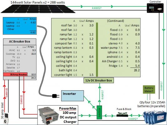
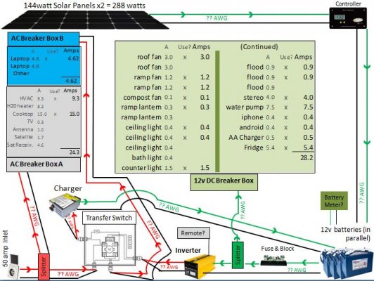
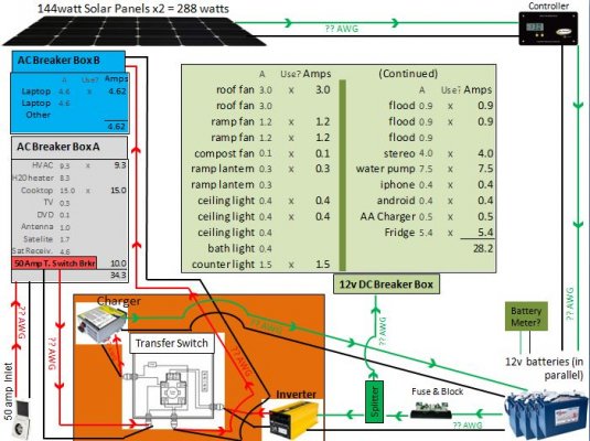
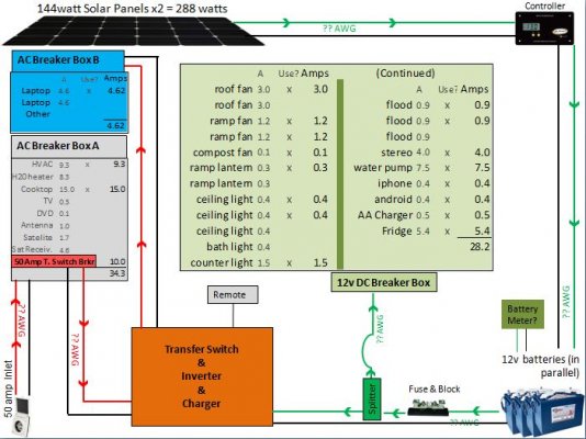
First post:  I am not an electrician by any means, but I am loosely diagramming my electrical setup in my new camper (picture attached).  I am patting myself on the back for making this diagram look good/ readable, but the praise stops there.  Does this plan actually function?  It is not too different from one I emulated at http://gpelectric.com/files/gpelectric/images/applications/How_Solar_Works_with_RV_by_Go_Power.png.  I was hoping you guys could take a quick look at this and tell me if I am going to fall flat on my face in some way.  2 questions come immediately to mind:

1)  Do the green and pink "splitters" (or junction boxes) near the bottom of picture work?  For the green 12v splitter, my intention is to bypass the inverter since many appliances (in light green) are 12v, and you lose efficiency through inverters.  For the pink splitter, I want certain appliances only available when plugged into shore power.

2)  Even though many websites have drawings similar to this, I feel like I am missing something at the battery connections.  Can I be charging the batteries while using them at the same time?

Thanks for any thoughts!
 

Attachments

  • rv wiring diagram1.JPG
    rv wiring diagram1.JPG
    89.2 KB · Views: 185
First, welcome to the forum. 
You've covered the basics pretty well, but my first thought would be to feed the shore power directly into Breaker Box A (eliminate the red "splitter" junction) and assign a breaker in Box A to feed the transfer switch.  This provides more protection for the camper wiring.

The way you have the diagram drawn, you will have all circuits, in both Box A and Box B, available with shore power.  You will have ONLY Box B circuits available from the Inverter.  I assume this is what you intended.

When you turn the Inverter ON, while plugged into shore power or not, Box B will be fed by the Inverter.  Again, I assume that's what you intended.  Do a little research into cable size requirements between batteries and the Inverter, and you'll be in business.

EDIT:  Considering the limited use and load that you have planned for the Inverter, I would suggest eliminating the transfer switch, and the extra sub-panel (panel B), and simply plug the laptops directly into the Inverter.  Extra expense and complexity are always good things to avoid where possible.

Good luck and happy camping. lou
 
Splitters is not the proper term, However junction box is.. You need to make a few changes to the diagram.

First, the Red/Pink J-Box (Junction) You may wish to do this split inside the Transfer switch, and put a master breaker on it right there, (This may require you modify the transfer box bu cutting a hole in the cover and adding a bracket to mount the breaker,, NOT all breakers are designed to go into a breaker box, some have two screw terminals)

As for the 12 volt side of things.. What you described is a very normal install  Including the green junction box.  Fuses or self-resetting or manual resetting circuit breakers are a very good idea any time a large wire (IE: Inverter to battery) feeds a smaller one.. Also the rules for inverters.. AS close as possible to the battery, but NOT so close they breath the same air, and put the two wires in a common LOOM on the dc side.

A better diagram for you on the 120 side, NOTE this takes care of your converter too...

Inlet--------Main breaker box (Breakers to loads) Big breaker to ----Inverter/charger---Sub breaker panel

And the 12 volt

Inverter/converter---Big "T" fuse---Battery--Smaller fuse or breaker----Distribution panel (Fuses).

THis type of converter (By the way please consider a true sine wave model) has a transfer switch built in.  It is what I have here I might add.
 
You can get an inverter/charger with a built in transfer switch that would simplify your wiring somewhat. Probably costs more than building your own the way you show it, though.

Here are a couple brands of them:
http://www.tripplite.com/en/products/product-series.cfm?txtSeriesID=820
http://www.xantrex.com/power-products/inverter-chargers/overview.aspx
 
Thanks for the replies!  Do I understand this right: My diagram will work, but it could be considerably more efficient?

Lou, I like the idea of getting rid of Breaker Box B.  Simple is better.  Thanks for that!  I may run some other things off the inverter one day but I can cross that bridge when needed.

John, I am not sure I fully understand some/most of that advice.  It "sounds" like it is probably good stuff, but I dont know enough to understand why.  Would you mind clarifying?  Example:

-  What will the split inside (rather than outside) of the transfer switch buy me?

-  My lack of electrical knowledge was evident when attempting to decipher the bottom half of your post.  Is there a drawing online of something similar?  After some time studying and googling, I thought I better ask for clarification first.

Thanks again!
 
Gary,
Just saw your post.  I am digging those combo units.  I also dont mind spending extra on simplicity since I am not an expert.  Also looks smaller and easier to install.

Need to crank one of those units into my thinking/ diagram now.  Thanks.
 
OK.  New diagram based on everyone's input.  If I use one of the "inverter/ charger/ transfer switch" combo units, my drawing looks like this (attached). 

The main changes are:
*    The encompassing transfer switch is the orange. 
**  For AC Breaker Box A, I have added a 50 amp breaker "pass through." 

The whole system would work like this: 

-  When plugged into shore power or generator, I have access to everything (obviously not all at the same time).

-  When unplugged, I only have the 12v appliances (green) accessible, as well as the items running off the inverter (blue).


Regarding the combo "inverter/ charger/ transfer switch"
Of the 2 units Gary recommended, a quick study has me leaning toward the Tripp Lite (mainly because its cheaper):  http://www.tripplite.com/en/products/model.cfm?txtSeriesID=820&txtModelID=3600

But my uneducated concern with this unit is that it says the max AC input is 120v at 38 amps.  If I plug into a campground with 120v 50amp, am I OK?  Or will I damage something?

Thanks again for any thoughts!
 

Attachments

  • rv wiring diagram2.JPG
    rv wiring diagram2.JPG
    90 KB · Views: 39
Your diagram is still unnecessarily complex in that your charger 12V output, and your Inverter 12V input, are the same connection on the I/C unit. 
Don't worry about the amperage rating on the 120vac input.  That is a capacity limit on the supplied power.  Your rig will only draw the amont of current it needs.  The incoming power has no way of forcing more current than your rig requires.
 
650nmwolf, could you tell us if this configuration is going into a hypothetical rig, or is it an existing RV?  If existing, can you give the make and model info?

Your drawings suggest a simple 30amp service requirement, yet you reference 50amp input power.  I'm sure some here (including me) are a bit confused on the design parameters.  Thanks in advance.
 
Lou,

Thanks again for taking an interest in my situation!

My thoughts:

-  Are you saying you can use the same wire for both DC input and output?  I have never really understood that since I have always envisioned electricity running in one direction like plumbing (needing a pipe for input and one for output).  Now that you say that, as I look at the drawing for this combo unit, it only has one connection for DC (#5 in attachment).

-  This is for a new hybrid toyhauler camper I just purchased last month.  It is sitting in my driveway ready for wires and equipment; I am trying to wrap my brain around the basics to see if I can tackle it all on my own, or if I have to take it to a local RV shop for the work.  If I cant do it myself (or dont trust myself), I want to at least know the major components and how they work so I can tell them exactly how I want it.
 

Attachments

  • tripplite snapshot.JPG
    tripplite snapshot.JPG
    37 KB · Views: 25
So for a redraw of what I think you are telling me...

Hopefully I have it right now.  If so, I am loving the simplicity and cleanness of it.
 

Attachments

  • rv wiring diagram3.JPG
    rv wiring diagram3.JPG
    78.6 KB · Views: 38
Clarifying your 50 amp vs 30 amp questions.  I elected for the 50 amp because:

-  I thought it couldnt hurt going with the larger amperage and might be a little safer and more efficient.  Is there a downside to it?  Do parks sometimes only have 50 amp?  Or if they have 50 amp, will they also have 30 and/or 15?  If they only had 30 amp or 20 amp, I thought I could use some adapters (like those attached).

-  I was planning for the unknown.  What if I wanted to run power tools, etc in the future?  I dont forsee it, but I was just trying to cover my behind.

-  Although my diagram (spreadsheet portion) shows only some of the appliances "running," if I turn more on, I COULD eclipse 3600 watts.

My decision to go 50 amp was also based on there not being a significant difference in cost of goods.  I know bigger wires and breaker would be required.  Any other drawbacks I am missing?
 

Attachments

  • amp adapters.jpg
    amp adapters.jpg
    35 KB · Views: 8
The diagram certainly looks better, however.....  Isn't there always another however? :)

Now for the however;  Your understanding of the differences in how 30amp and 50amp RV service is delivered/utilized is a little fuzzy.
  • 30amp RV service is a single 120vac, 30amp rated, feed.  All components, from source to your main Breaker panel, must be sized to handle up to 30amps.  Wire size = 10awg, plugs/receptacles and breakers/fuses rated for 30amps.
  • 50amp RV service is two (2) 120vac, 50amp rated, feeds.  (100amps total)  All components from source to main breaker panel must be sized for 50amps.  Wire size = 8awg with all plugs, receptacles and breakers rated for 50amps.
The greatest physical difference will exist at the main breaker panel.  For 50amp service, everything is in duplicate.  The 50amp panel will require two main breakers (one for each feed) and each will feed a selected set of branch circuits.
I couldn't even guess the ratio of 30/50 amp service available in CGs/Parks these days.  My gut feel is that 30amp will be around for a good long time for us older and/or smaller RV owners.  I would suggest that you only need 30amp service.
BTW - There are much better explanations of the different levels of RV electrical service available on the internet with a few Google searches.
 
Regarding the 38 amp max to the inverter's internal transfer switch.

NO problem at all, Your 50 amp cord goes to the main breaker box, a 30 or 35 amp breaker goes from there to the inverter/converter.  This smaller breaker protects the Inverters and it's transfer switch..

This is exactly how my RV is wired.  Save I also have a generator.

But if you leave out the generator and its transfer switch

50 amp cord to park---Breaker box---Breaker---Inverter--Breaker box 2---Breakers--TV, Microwave, Computers, GFCI and all things inverter powered.
 
I am sorry, John...slow down. You are making my head hurt. Use the KISS method.
 
  (I'll probably regret writing this rant)

 
Wait a minute!  Can I make this even simpler!  My sticker shock at the combo units ($1000+) caused me to rethink this.  Is it as simple as the following picture below?  Maybe I am missing something, but the uneducated electrician in me is thinking this might really work.  Any thoughts?

Edit:  Disregard the AWG numbers.  I need to go bigger on the 12v side.  Everything is within a few feet of each other, but I still need bigger.  I am thinking #4 or more.

Edit 2:  changed 100 watt to amp
 

Attachments

  • rv wiring diagram5.JPG
    rv wiring diagram5.JPG
    81.2 KB · Views: 32
Absolutely it will work.  I'm not sure your choice of converter/charger is optimum yet, but you have a much better handle on it than before.

If you go back and read my first reply, you will see that this was my first suggestion.  It's good that you worked through it yourself and now understand your own requirements better.
 
Comparing your photo of the Power Max charger with their product line, I'm going to guess that you meant 100 amps, rather than, 100 watts.  My personal thoughts are that you don't need nearly that much from a charger.

A quality three stage 45amp converter/charger would be a good choice.
 
Thanks for catching the watts/ amps mistake.  I just fixed it.

I did comprehend your initial "direct to inverter" suggestion, but the "lose the transfer switch" part I somehow glossed over.  Part of it was my inexperience with the subject.  My what 4-5 days researching can do.  Thanks to you (and some others), I can now pass Electricity 101.

The reason I am leaning to the 3 stage (I think they even offer a 4 stage) 100 amp model was for faster charging for not that much more cost.  I think the max amperage I can charge is at 20% of my total battery Ah rating (155Ah x 4 batteries = 620Ah x .2 = 124 amps).

Are there any drawbacks other than price when going with a 100 amp unit vs a 45 amp?  Maybe requiring heavier gauge wires?
 
I was just trying to be practical.  A 60, 80 or 100 amp multi-stage charger is fine.

You most likely will never see it charging at a rate above 30 or 40 amps, however.  You will not want to drain your batteries down below 50 or 60%, so they won't require maximum current to recharge and the current will quickly taper off as the charge progresses.

Remember it's the battery that regulates the amount of current, not the charger.  If the battery doesn't require a heavy current charge, the charger can't force it to accept more.  I guess large chargers are nice if/when your batteries suffer a deep discharge and need a quick recharge.   
 

Latest posts

Forum statistics

Threads
131,973
Posts
1,388,466
Members
137,722
Latest member
RoyL57
Back
Top Bottom