"Pretty" Electrical Diagram, but does it work?

The friendliest place on the web for anyone with an RV or an interest in RVing!
If you have answers, please help by responding to the unanswered posts.
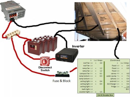
I have done a little more research and made 2 small changes:

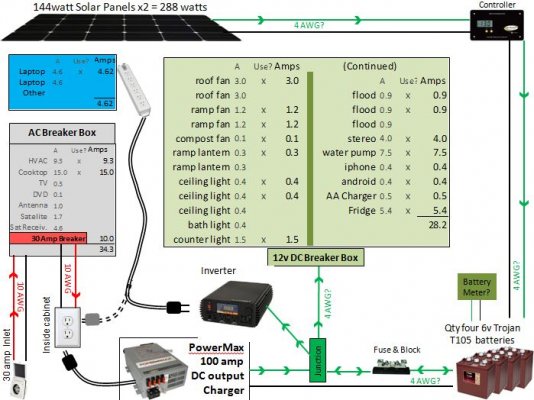
1)  I decided to go the 6v (Trojan 105) in series route rather than the Duracell 12v 155 Ah (http://www.samsclub.com/sams/duracell-golf-car-battery-group-size-gc12v/prod3870120.ip?navAction=push).  I simply made that call based on some comments on this board and the popularity of it.  The 12v offers A LOT more Ah, but I will go with the proven winner.

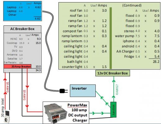
2)  Made the red breaker going to my charger a 20 amp instead of a 30 amp.  The Powermax charger I chose draws a max of 13 amps.

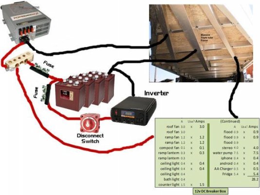
My new question, and I think I know the answer, is what if I delay my purchase of batteries, solar, solar controller, etc and just use shore power this year?  This will be my family's first year at campsites, and I believe we will not be venturing away from shore power.  Seems like this would work fine; then I could make the large investment in the other items next year.

Do you guys forsee any issues when my drawing looks like this.
 

Attachments

  • rv wiring diagram7.JPG
    rv wiring diagram7.JPG
    62.5 KB · Views: 21
Ditch the solar, but not the batteries.  You'll need at least one 12 volt battery in your toyhauler - it's a legal requirement so you have power to activate the trailer brakes via the breakaway switch if the trailer ever detaches from the tow vehicle.

If you conserve power you'll be able to boondock for a night or two on battery power without having solar to recharge them.

You'll also want 12 volt power available while underway to run the circuit board in the refrigerator, maybe run a light or ventilation fan, the water pump (to flush the toilet, wash your hands or dishes) etc. when you stop for lunch.
 
It appears that your laptop only gets power via the inverter, so without a battery you have no stable power there. The inverter may be able to draw from the converter/charger as long as the 12v output stays up continuously, but having at least one battery attached would stabilize the power better (a battery acts as a big 12v power filter as well as storage).

Why not leave out the inverter as well - it serves no purpose without batteries? Just run a wire from a breaker the main AC breaker box to the secondary box for the computers until ready to add batteries and related gear.
 
The comments from Gary and Lou S. are all valid considerations.  You definitely need a battery.  Your choice of two 6V, in series, is a good one.  I also see no need for the solar if your camping is nearly always with shore power.
 
OK.  Refining.  Solar will wait til next year, but I am going with 4 or 6 batteries (probably 4).  Here is what it looks like now...
 

Attachments

  • rv wiring diagram9.JPG
    rv wiring diagram9.JPG
    82.3 KB · Views: 22
Now for my next question.  Is the 12v green junction box (above) also referred to as a distribution block?  Do I have a distribution block for positive and negative?  Would the wiring after the charger look like this?

EDIT:  pay no attention to the way the batteries terminate.  I need to study up on that and I will post my thoughts.  I know two 6v in series give me 12v, then the 2 or more 12v "mini battery banks" in parallel to increase my Ah.  I just need to figure out how it all connects together.  Thanks!
 

Attachments

  • rv wiring diagram9 blocks.JPG
    rv wiring diagram9 blocks.JPG
    31.6 KB · Views: 14
Keep the inverter as close to the batteries as possible (reasonable).  You might want to consider increasing the size of the connecting wires/cables between batteries and inverter if the distance becomes a problem.

As for the negative distribution block or point, the trailer frame makes a great negative return path/buss and the total accumulation of ground connections is rarely returned to a single point.  However, I would suggest that both the positive, and negative, connections to/from the inverter, be made directly to the batteries.
 
I haven't been following this discussion in detail, but I suggest you add a battery disconnect switch between the batteries and the inverter. One like this will work fine.
 
Thanks for the thoughts guys!  I made some new changes the the wiring details.  I terminated to my trailer frame at multiple points and connected the inverter directly to the batteries.  I also added the disconnect switch.

My new question is:  Since I have an all aluminum frame, is this still a good ground?  I know steel would be best, but I don't have any big chunks of it attached.
 

Attachments

  • rv wiring diagram9 blocks2.jpg
    rv wiring diagram9 blocks2.jpg
    40.4 KB · Views: 16
Your original diagrams had a fuse in the circuit off the batteries. You need to add the back the fuse between the batteries and the  positive distribution block.

Aluminum is a good conductor.

ken
 
Lookin' good.  Don't forget to include that fuse/Block between the battery plus (very close to the battery) and the inverter in your final design.

I think you have absorbed a lot of the basics while going through this exercise.  Just keep the configuration and diagram as simple as your power requirements will allow, and you will do fine.
Good luck with getting the project finished.

EDIT - I see Ken noticed the missing fuse as well.  A large fuse needs to be between the batteries and the Inverter, but a smaller fuse between the batteries and distribution panel is also advised.
 
Oh Boy...let me get into trouble again.

  Great exercise in inventing this system from scratch. Looking nice.

Inventions start in the brain. Then they are put on paper; drawings are made and re-analyzed.

Next step is normally to build a prototype on the bench and make a dry run. Then..
the testing starts to prove the safety, reliability and performance of the system. Then..
if proven workable and stable, install with meticulous workmanship.

OK, I admit to being a bit over the edge.  I hope all new systems are done that way which can include about anything you buy that is supposed to work for a long time.

T'was a nice thread to follow.

 
Good to know about the aluminum and thanks for catching the fuse omission.

Can that fuse go anywhere in the circuit?  I assume it has to be on a positive wire.  How about here?
 

Attachments

  • rv wiring diagram9 blocks3.jpg
    rv wiring diagram9 blocks3.jpg
    41.5 KB · Views: 19
You should have a fuse on any lead off you batteries. In your diagram you should have a fuse between the batteries and the inverter and another between the distribution block and the batteries. The fuse should be sized to the smallest wire that it is protecting.

ken
 
Ken is correct, and it can't be stressed enough that the fuse should be located as close to the source (the battery) as possible, because it's the wire that is being protected.  You never know if/where a short is going to occur in a circuit, but you want the blown fuse to remove the positive potential from as much of the circuit as it can.  He is also correct in that every wire connection to the battery should be protected by a fuse.
 
OK.  Slowly but surely, I am getting this.  I cant thank you guys enough for taking an interest in my project.  This is awesome!

In my last drawing, somehow I missed the "close to battery" message you guys sent me.  I have corrected that and put another on the second wire connection.

I assume that the fuse only needs to be on the positive wire since a blown fuse will break the entire circuit on all wires.
 

Attachments

  • rv wiring diagram9 blocks4.jpg
    rv wiring diagram9 blocks4.jpg
    41.4 KB · Views: 15
650nmWolf said:
I assume that the fuse only needs to be on the positive wire since a blown fuse will break the entire circuit on all wires.
That is correct. In fact it is not a very good idea to put a fuse or a switch on the ground or neutral wire. In fact it is even illegal according to the electrical code.
 
Great!  I think the final question (for this portion) I have is in regards to wire gauge thickness.  I can calculate the gauge needed from each appliance back to the breaker.  What I am a little unsure about is the wires in this final drawing (connecting charger, distribution block, fuses, batteries, inverter, DC breaker box, and all grounds).

Shall I just go with the largest I can practically work with?  My longest run will be about 4.5 feet.  Can I just go with 4 gauge on everything?  Should I go thicker for safety?  I am not sure I can even connect something that thick to my inverter, but maybe I can?
 
650nmWolf said:
Shall I just go with the largest I can practically work with?  My longest run will be about 4.5 feet.  Can I just go with 4 gauge on everything?  Should I go thicker for safety?  I am not sure I can even connect something that thick to my inverter, but maybe I can?
Number 4 should work fine.
 
To answer this question we need to know the Inverter output in watts or amps and the charging capcity of the converter. You already show the 12 loads at the panel.

ken
 
Back
Top Bottom