Hidden circuit breakers & solenoid access - Adventurer 35U

The friendliest place on the web for anyone with an RV or an interest in RVing!
If you have answers, please help by responding to the unanswered posts.
Status
Not open for further replies.

Bill N

Well-known member
Joined
Jan 4, 2014
Posts
2,551
Location
Ozark, Missouri
Sorry to look like I am posting more than my fair share of threads but I appreciated the help of the experts and others in solving the problems of a newbie.  Now I would just like to post some information that may in the future help others who come into ownership wide eyed and ignorant.
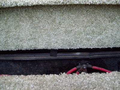
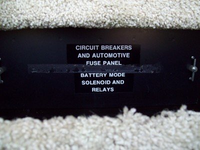
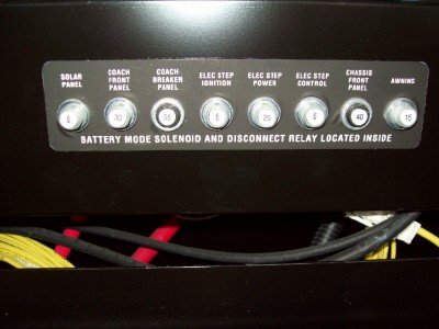
While planning on replacing the pair of 6 volt house batteries on my 2002 Adventurer 35U, I pulled open the step under which they are located and saw how easy a job it will be.  Then I noticed a little black tab hanging down from the vertical carpeted board above the step and gave it a little tug upon which it immediately fell down.  It was held in place by a velcro strip that pulled loose from the backing.  Behind that was a metal door with two quick release handles and some decals noting this was an area for battery circuit breakers and solenoid access (not exact phrasing).  Opened that little panel and sure enough there are five or six circuit breakers mounted on a panel with ID decals for each of them (can't remember names at the moment). I do remember one was for the awning and three were for, as best I can recall, the sliders but that may be wrong.  It was also obvious that this panel was only held by 4 screws and a lot of wiring and connectors were behind it.
The point here is none of this was mentioned in the owners manual and could be of interest to the owner who is trying to trouble shoot a specific problem but can't find the proper circuit breaker, solenoid or wire connection.  I may try to take a photo later this morning but others may be able to better explain this area.
 
I tried to attach some photos and thought I had them downsized below 250kb but evidently not so if anybody wants them, drop me an email and I will attach them for you.
 
Bill N said:
The point here is none of this was mentioned in the owners manual and could be of interest to the owner who is trying to trouble shoot a specific problem but can't find the proper circuit breaker, solenoid or wire connection.  I may try to take a photo later this morning but others may be able to better explain this area.

This is really not an owners' manual issue. Most owners really shouldn't be messing around in this box.

Notwithstanding, you will find a full detailed schematic, and comprehensive physical wiring layout on the Winnebago site.
 
With all due respect Stan, it is my coach lock, stock and barrel and I should be told where circuit breakers are located.  Why did they take the time to photograph and explain the location of all the breakers inside the coach both for 12v and 110v?  It is definitely an owners manual item.  There are eight breakers in that location, one for the awning, three for the steps, one for the solar panel, one for the coach front panel, one for the house front panel a 55 amp breaker for the coach breaker panel.  You are probably much better than me trying to read their wiring charts but there is no reason I should not know the location of major circuit breakers in the coach.
 
Bill N said:
With all due respect Stan, it is my coach lock, stock and barrel and I should be told where circuit breakers are located.

Sorry. I was not referring to the circuit breakers; only the schematics wiring for the solenoid box, which isn't accessed on a day-to-day basis by your average user. Most circuit breakers are located under the dash, under the the front engine, or in the coach somewhere around the stove, under the fridge, ATS box and on the generator.   
 
Here is another try to post photos.  I have reduced them to web size and hope they can be opened to a larger size.
 

Attachments

  • Step partial open -1.jpg
    Step partial open -1.jpg
    56.9 KB · Views: 30
  • Panel Behind vertical board-1.jpg
    Panel Behind vertical board-1.jpg
    93.1 KB · Views: 34
  • Circuit Breakers behind panel-1.jpg
    Circuit Breakers behind panel-1.jpg
    89.6 KB · Views: 43
Bill N said:
..The point here is none of this was mentioned in the owners manual and could be of interest to the owner who is trying to trouble shoot a specific problem but can't find the proper circuit breaker, solenoid or wire connection.  I may try to take a photo later this morning but others may be able to better explain this area.

Well, it is what it is.  Winnie decided not to include that kind of information for whatever reason.  I agree, it is valuable info for those who are technically capable, but tech help from Owner Relations is only an email or phone call away.

Back to that area - the battery mode solenoid is the solenoid (it's a continuous duty relay) that operates when either the Battery Boost switch is operated or when the engine is running, it parallels the house and chassis batteries together primarily for charging when the engine is running.

The circuit breakers are self-explanatory.
 
John, I have to take exception to your term "technically capable". Sounds Winn appologist to me. Surely the great majority of owners are capable of finding and resetting an important breaker! If not, why document the location of the other breaker panels?

This is simply an example of bad technical writing. That said, I must acknowlege that Winn overall does an excellent job of documentation.  Few people appreciate how difficult and expensive it is to provide accurate and complete technical documents.  I'd estimate, and I wrote and quoted this stuff for years, that they spend between $150 and $200 for every page of that documentation not counting printing costs!

Ernie
 
Ernie n Tara said:
  Few people appreciate how difficult and expensive it is to provide accurate and complete technical documents.  I'd estimate, and I wrote and quoted this stuff for years, that they spend between $150 and $200 for every page of that documentation not counting printing costs!

Ernie

I agree Ernie. During my Air Force career I was a missile launch officer and everything we did was in accordance with a specific technical order and checklist.  Those documents were maintained letter perfect and at great expense no doubt but the consequences of going to a missile launch checklist and finding a blank spot where it should have said "Turn Key" could have serious consequences ;D  Now I need to make another post to see if anyone can help me figure out what modifications my previous owner made to the WH plumbing that leave me baffled (not a hard thing to do)
 
Just to add to what John has said: There is a reason these components are all secured inside a heavy duty metal electrical box; and also why you will find some of the info in the online Winnebago electrical sheets, and other information in your Ford chassis service manual. This is where the house and chassis electrical systems are wired together through a couple of heavy duty relays, that carry some really SERIOUS current . . . in the order of 100s of amps.

One simple mistake by someone who doesn't understand the power that can be unleashed by that box could end up melting much of the wiring in the chassis and coach, with a very high potential for setting the rig on fire, not to mention serious personal injuries.

I have worked on that box, replacing the constant duty solenoid, while I was in some WalMart parking lot out in the boonies on Vancouver Island. I consider myself to be "technically capable", and as such, ALL of the Winnebago service material was already installed and available on my computer, in addition to the full Ford service manual for my F53 chassis. An essential aspect of being "technically capable" means having the tools and knowing how to use them! And IMO having the tools means having having all of the technical and service data available before you actually need them.

I have been maintaining my aged Winnebago through thick and thin over the past 15 years, and IMO Winnebago is light years ahead of any other RV manufacturer for providing customers with the necessary technical data to keep the rig on the road!
 
I thought I was doing a favor to post the location of those circuit breakers.  I never insinuated that you go behind them to the solenoids,etc, unless you knew what you were doing. But God gave me 10 fingers, each of which is capable of resetting a circuit breaker if it is popped.  If I had never seen these circuit breakers I would not have known where to reset an awning problem or a step problem or even something as minor as a solar panel problem.  Believe me, I passed up several other brand of coaches to have a Winnebago because of their reputation.  But nobody is perfect and there are some obvious things overlooked in the owners manual.  For example, something as simple as the electric controls on the driver and passenger seats are never discussed or even pictured.  Just the two manual levers are shown.  The 12 volt circuit breakers above the microwave are only given general labels such as lamps but you have to be an electronic schematic reading expert to trace some of that wiring to find which specific CB controls what item.  I guess you just wait until it pops to see what it controls.  In our houses, the breakers are identified by specific item controlled.  As for Winnebago service center help, I scored a 50 percent success rate on my recent request for help.  After describing my lamp wiring problem and asking for a possible location of a connector, I was told to look in the wiring diagram (which I had told them I had already done).  I asked for location of solenoids for the sliders and was sent a link to a diagram where the word solenoid never appeared.  Thankfully, several of the forum members here provide answers to questions because they themselves have had the same problems and found solutions.  A lot of what is overlooked is designed to be that way in order to give the dealer service centers the business and I suspect these circuit breakers are in that category.  Of course this is all JMHO but I have managed to collect all of the Winnebago manuals, charts, diagrams for the various systems and use them often but none of them match up to a conversation with someone else who has already had the problem and knows the solution.
 
I think that over the years Winnebago has improved the amount of info in the Owners Manuals (in addition to the wiring, etc. diagrams).  Although  those chassis circuit breakers aren't listed in your 2002 manual, the manual for my 2005 Vectra does in fact identify where the chassis breakers are along with a picture (left front compartment).  There are still a few things in other (unidentified) locations on the chassis, such as the trailer wiring breaker hidden away in the left rear corner behind a screwed down side panel, but they are doing better overall.
 
Bill, never hesitate to post information that you found useful and that you think others may find useful. It is up to the reader to determine whether or not it is something they can use. Even though they might not be comfortable getting into the breaker/solenoid compartment, they can point out the location to a service person or helper. Within a model such as Adventurer and year, there can be several variations that are hard to document in the manual. The manual is more a How to "Use the Motor Home" manual, than a "How to Fix and Trouble Shoot the Motor Home" manual.
 
Bill N said:
The 12 volt circuit breakers above the microwave are only given general labels such as lamps but you have to be an electronic schematic reading expert to trace some of that wiring to find which specific CB controls what item.  I guess you just wait until it pops to see what it controls.

Just waiting until the circuit breaker pops up sounds like a pretty good option for the many RVers who are not "technically capable". If it doesn't pop up, then all well and good; no action needed. If it does pop up, then time to consult someone "technically capable".

For those who are even modestly "technically capable". Winnebago makes it an absolute breeze to troubleshoot electrical problems. Each and Every wire in the entire rig is coded, and the intent and purpose of each and every wire in the rig can be found in Winnebago's Wiring Codes Electrical Guide which looks like this:

Wiring Codes Electrical Guide

TTY / 18 YEL CHASSIS BATT DISCONNECT RELAY (TERMINAL I)(POS-ENGAGE) CHASSIS BATT DISCONNECT SWITCH
TTZ / 18 YEL CHASSIS BATT DISCONNECT RELAY (TERMINAL S)(POS-DISENGAGE) CHASSIS BATT DISCONNECT SWITCH
UUA / 18 YEL CHASSIS BATT DISCONNECT RELAY LOAD SIDE FUSE FEED CHASSIS BATT DISCONNECT SWITCH INDICATOR LAMP
UUB / 18 YEL CHASSIS BATT DISCONNECT LOCKOUT RELAY-NC CONTACT CHASSIS BATT DISCONNECT RELAY SWITCH
UUC / 18 WHT CHASSIS BATT DISCONNECT SWITCH GROUND


Since this detailed user manual, provided to Winnebago owners runs some 29 pages, I'm not quite sure what you had in mind when you say: circuit breakers above the microwave are only given general labels such as lamps. I'm not at all convinced that printing all 29 pages on the circuit-breaker panel would add anything useful for user clarity.  ::) 
 
I think I am about done with this thread  but now I do know where to look if my awning loses power or the steps are not functioning right or if I want to isolate the solar panel.  Possibly a few others have also found out something new about their coach as that was my original intention in the posting.
 
Status
Not open for further replies.

Latest posts

Members online

Forum statistics

Threads
131,954
Posts
1,388,150
Members
137,708
Latest member
7mark7
Back
Top Bottom