Automatic Power Switch problem

The friendliest place on the web for anyone with an RV or an interest in RVing!
If you have answers, please help by responding to the unanswered posts.

Zertman

New member
Joined
Jul 6, 2014
Posts
4
Hi Everyone!
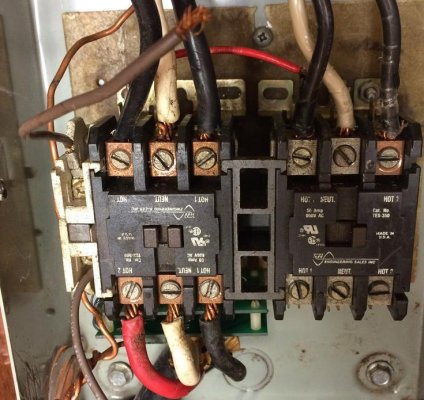
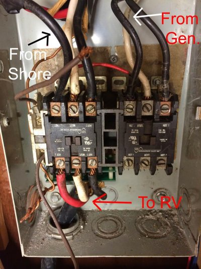
I have a Country Couch motor home that I am having a problem with the automatic power switch.  It switches the AC power going to the RV from either shore power or the generator.  I have AC power coming in from the shore power into the switch but its not keeping the power connected to the RV.  The switch has a push-in button on the front.  If I push the button in, it connects the power to the RV but if I let it go the button will pop back out and stop the power.  The switch also has two brown wires (shown in the pic) coming out of it but are not connect to anything because I didn't know where they should be connected to.  I'm guessing the problem is due to those wires not being connected to where they should be.  The picture shows three groups of large wires connected to the switch: top left is from shore, top right is from the generator, and bottom left is to the RV.  Please someone help with this problem.
Thanks!
 

Attachments

  • IMG_0167 3.jpg
    IMG_0167 3.jpg
    87.4 KB · Views: 56
In this a "new to you" vehicle by any chance?? Did this ever function to your knowledge?

Do those brown wires show any evidence of ever being connected?? (The top one looks like it may have been twisted into a wire nut perhaps or pulled out from under a terminal similar to those others, but in any event it should not have been left bare). If so, the proper place can't be too far away and may reveal itself with a closer examination. They are likely the wires that activate that ATS (Automatic Transfer Switch) as you suspect. If you run the generator do you get power inside??
 
I'm NOT familiar with this particular switch, but I doubt the brown wires are the problem. They seem to be ground wires, as are the bare wires and would not normally be required.

The switch should normally pass the generator output to the coach and connect the shore power only when the generator is not running.  I would expect that the red wire may activate the switch when the generator is running to ensure it has priority.

The symptom you are describing is that of a circuit breaker operating. Perhaps the two buttons on the left side of the switch?

I think the test should be (only if you are comfortable working with high voltage) to disconnect the house side wires and then measure the voltage where they were removed, both with and without the generator. Output should be 120Vac between either HOT and NEUTRAL. If you get the correct voltages, there is likely a short in the house wiring; if not the switch/relay is defective. If pressing the button still provides momentary output the switch/relay is likely bad.

Remember I am NOT familiar with this particular switch!

Ernie
 
I'm in agreement with Ernie on this.

The pushbutton is almost surely a circuit breaker and it is opening because it is supposed to when it detects and overload (short circuit). The trick is to figure out where.

Is the pushbutton you mentioned the one(s) in the left side of the photo? I've not seen an auto transfer switch with a breaker built in, but I've not seen that model of ATS before either.
 
This looks like a common AC contactor. The push button is a manual push button for trouble shooting purposes. The brown wires are the pull in coil wires. There may be a diagram on the side of the contactor that would help identify them.  If the system is made to pull in when shorepower is attached they probably go on the black and white shorepower wires.
I am sure that there are several others who may know more of how this system works.
 
The switch on the side is not a circuit breaker.  It is as boatbuilder said. 
Here is a diagram of how the TS should be installed.

I am curious if this is being replaced/installed by the OP or if it has always been hooked up this way, because I think the incoming and outgoing wires may be hooked up wrong. 
 
If the diagram that Just Lou posted is the correct one, and it looks like it is, it looks like the switch is wired incorrectly. The instructions say the side switch should be on the generator side. It doesn't specify where te brown wires go but in the parts list they show two 16ga brown wires. One has a female QC terminal on the end and the other has a female flag. This leads me to believe they get hooked up to the contactor.
I would also test the interlock per the instructions.
 
That switch is put in the circuit to ensure that the shore power contactor is fully dropped out before the generator contactor can close.  It is mechanically interlocked with the armature of the contactor, just as the two contactors are interlocked between each other, to prevent simultaneous activation.

Here's another document and diagram that may help.
 
Thanks for the help.  I think I must have put the switch on upside down because the wires are to short and rigid to be connected anywhere else on the switch.  So I should connect the brown wires the to shore power?
 

Attachments

  • IMG_0167 4.jpg
    IMG_0167 4.jpg
    151.8 KB · Views: 23
Zertman said:
Thanks for the help.  I think I must have put the switch on upside down because the wires are to short and rigid to be connected anywhere else on the switch.  So I should connect the brown wires the to shore power?
NO, do not connect them to the shore input.  Electrically, the switch interrupts the picking of the generator contactor until the shore contactor is fully open.  Exactly how they are wired into your unit, I can't tell from your photo.

They probably go to some of the circuit board connectors, but I'm not sure just which on your unit.  The newer boards are larger than yours appear to be.
 
I tested the side switch using a volt meter.  It reads a open across the leads without pushing the switch down.  Does this mean that the side switch is bad?
 
Zertman said:
I tested the side switch using a volt meter.  It reads a open across the leads without pushing the switch down.  Does this mean that the side switch is bad?
NO, it means that it is GOOD.

Of course, it is not hooked up now so it is currently accomplishing nothing....., but if it were installed correctly, and the contactors were installed correctly, and they were working correctly, the switch would be open when the shore power contactor was activated.  It would not close again until the shore power contactor de-activates to allow the generator contactor to activate.

It is mechanically interlocked to prevent both the shore and gen contactors to apply power to the coach at the same time.  The contactors, themselves, are also interlocked to prevent this, but the addition of the switch prevents them from even attempting to activate at the same time.

Your safest course of action would be to purchase a new transfer switch and have someone install it.

BTW - that switch is not meant to be activated by pressing on it.  It is activated by the contactor armature movement.t
 
Huh, really? That not what the troubleshooting guide that you posted says.  Am I reading it wrong?
Quote:
"Check side switch for proper operation. This switch is located next to the Generator contactor. Be sure the leads are securely fastened to the switch and the switch is firmly seated against the contactor. Using an ohmmeter, attach the test leads to positions S1 and S2. The meter should read 0 Ohms. Push down on the black rectangular ?button? located at the top of the switch. The switch must move freely up and down. In the down position, the ohmmeter should read open circuit. If either test fails, the side switch is bad and must be replaced."
 
Zertman said:
Huh, really? That not what the troubleshooting guide that you posted says.  Am I reading it wrong?
Quote:
"Check side switch for proper operation. This switch is located next to the Generator contactor. Be sure the leads are securely fastened to the switch and the switch is firmly seated against the contactor. Using an ohmmeter, attach the test leads to positions S1 and S2. The meter should read 0 Ohms. Push down on the black rectangular ?button? located at the top of the switch. The switch must move freely up and down. In the down position, the ohmmeter should read open circuit. If either test fails, the side switch is bad and must be replaced."
The troubleshooting guide also assumes the unit is assembled correctly.

By your own admission, you have the shore power going to the contactor adjacent to the switch.

What I meant was, the switch is activated by the contactor armature movement.  YES, you can TEST the switch for continuity by pressing on the button, but the button has no other purpose.
 
Back
Top Bottom