DC/AC Inverter Installation

The friendliest place on the web for anyone with an RV or an interest in RVing!
If you have answers, please help by responding to the unanswered posts.
Here is a LINK to a Xantrex web page which explains it. Yes, a single positive and negative square wave could be considered a modified sine wave, but the more steps you have to each positive or negative swing, the more closely it matches a true sine wave, and the happiere your appliances will be. ;)
 
I am curious just how many steps there really are in our inverter outputs.  Have you put your 'scope on yours?
 
I'll answer my own questions

--------------------------------------------------------------------------------

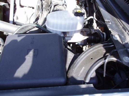
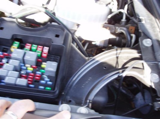
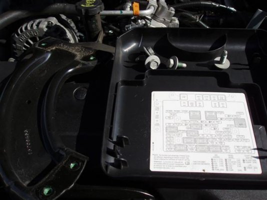
All directions in this reply are given as if standing in front of the drivers side front tire, facing the engine; there are four photos attached. Photo one shows the corner brace that must be removed, in order to lift the box that covers the wires off. The fuse is a 40 amp J fuse and is identified as "Stud 1," it's the first fuse top-left. Photo two shows the fuse box cover removed and the corner brace. Photo three shows the removed brace and fuse box cover resting on the radiator.
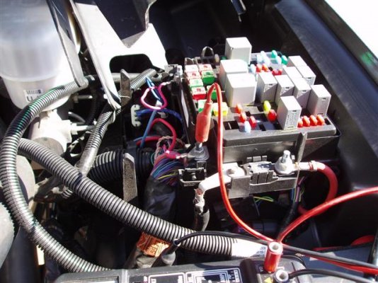
After the corner brace is removed, there are two **** on the lower front of the fuse box, facing the engine. Press those two **** in and you can pull UP on the fuse box and slide it to the right. You must slide it to the right because there is another wire attached to the outside right, there is plenty of slack in that wire. Photo four shows the box removed and exposes all the wiring, the photo is taken from the front of the truck. Now it makes sense, "Stud 1" is the stud my red test lead is clipped onto. The red wire attached to "Stud 1," is the feed for pin 4 of the 7 pin connector on the rear bumper. This is where I will install the feeds for my Ammeter.
 

Attachments

  • GMC Ammeter 004 (Small).jpg
    GMC Ammeter 004 (Small).jpg
    54.9 KB · Views: 13
  • GMC Ammeter 003 (Small).jpg
    GMC Ammeter 003 (Small).jpg
    53.4 KB · Views: 10
  • GMC Ammeter 001 (Small).jpg
    GMC Ammeter 001 (Small).jpg
    46.5 KB · Views: 11
  • GMC Ammeter 002 (Small).jpg
    GMC Ammeter 002 (Small).jpg
    73.4 KB · Views: 10
Hi Karl -

That's interesting - traditionally modified sine wave has meant a single stepped waveform as shown in this Trace PDF from a couple of years ago.

A Google search found this article from August 2006 describing the multiple stepped waveform.  I wish the author well with his patent application. <g>

I've found the single step waveform to be much more common in stand-alone inverters.
 
Lou, that was my belief too, that the inverters put out the single step modified waveform.  I guess it's time to put a scope on my AC inverter output.  Another QZ project, check all inverter output waveforms :)
 
Lou,
Agreed that single step is most common, but multiple steps have been around for years. The article is interesting, but people are already using fourth-order Fourier applied to the Helmholtz equation to study problems with partial differential equations. His 'solution' still doesn't address the dead zone at zero-crossing, but the adjustable time variables seems to have some merit. A pulse-width modulated  H-bridge operating at a fairly high frequency may also be of some use to minimize this.

Geez, my head is starting to hurt! ::)
 
Ned

>> Another QZ project, check all inverter output waveforms<<

I'd like to see the output on my 3000 pure sine wave inverter.
 
Boy, is my face RED! I thought I remembered scoping the output of my inverter a few years ago and seeing that stepped waveform, but something kept nagging at me so I checked it again a little while ago. Yep. Single step! Must have gotten some address lines in the gray matter crossed :-[  I was remembering a closed-loop controller I was working on back then. Sorry!

Terry,

Yep, we can sure do that. Curious to see what my little 600 watter looks like too. I should have that info today or tomorrow.
 
I don't know of any modified sine Rv inverters that are multi-step. Will be interested to hear if you find one.

I suspect the "pure sine' models are really just many-multiple step designs, with enough steps so that the wave is very close to "pure". You really need a winding rotating in magnetic field to generate a truly pure sine wave - everything else is an imitation, no?
 
Gary,
I suspect the "pure sine' models are really just many-multiple step designs, with enough steps so that the wave is very close to "pure". You really need a winding rotating in magnetic field to generate a truly pure sine wave
Can't really say for sure until I put the scope on it tomorrow. Then I'll look at a single cycle and expand it as much as possible and report back. I'll look at it both no-load, and with a 250W resistive load (heat lamp). Finished the installation and the primary side this evening. Touched the power cables onto the batteries and got a fairly large spark! Thought I had gotten the polarity wrong and destroyed it, but then remembered in the installation instructions they said there would be an initial high current draw to charge the capacitors. Touched it in again, turned it on, and everything was fine.
everything else is an imitation, no?
Some time ago, I did some experimentation with a large inductor (the secondary winding of a 60A battery charger transformer) and some large capacitors and a few transistors, and was able to get a pretty good, non-stepping approximation of a sine wave. Problem was that it only looked truly good for a very narrow range of load currents. A saturable core magnetic amplifier might do the trick, but that'll take a lot more experimentation and math. Like I said before, my head already hurts ;D
 
Rest your weary head, Karl. I certainly wasn't suggesting that anybody invent an electronic pure sine generator. Was just commenting that a mechanical, rotating genset is inherently pure sine and everything else jumps through hoops trying to mimic that inherently smooth action. Of course, if Edison had started with electronic rather than mechanical generation 100+ years ago, pulse width modulated square waves would be the norm and a "pure" sine wave the anomaly.  A classic case of historical determinism.
 
Update on the 600W sine wave inverter. Install done except for running the 120VAC back to the bedroom. Test results were good. With no load, frequency was 61Hz, scope signal was very clean except for a slight 'bubble' of about 6 volts for 23ms. on both the upslope of the positive side of zero, and the downslope on the negative side of zero. I estimate this distortion to be less than 3%. No sign of overshoot or ringing anywhere! 250W resistive load looked the same. Ran a 780W universal motor (vacuum cleaner) for about 10 minutes with no sign of overload or overheat. Heck, the cooling fan didn't even come on (the case is all heatsink with the exception of the bottom cover, which is just sheet metal). Waveform showed hash on both positive and negative slopes, but running on shore power showed the same hash. That was to be expected. Running under load, the frequency locked on at 60Hz. Conclusion: Quite frankly, I didn't expect to see such a clean and well controlled waveform. The continuous running over the rated 600W continuous rating without a hitch was also a nice surprise. All in all, I'm pleased with this unit. Whether it holds up in the long run is yet to be seen, but an inspection of the inner workings (motherboard; if you will) showed it to be well designed and built - good component placement, reflow soldering done cleanly and with no sharp wire ends, no sign of hand-wired rework or mod's, solder side had conformal coating. The only problem I had was with the supplied terminal ends for the primary power. Sized for #2 AWG, the flat end that was to be inserted into the screw terminals was slightly too wide, and required getting out the trusty old Dremel tool to take a little bit off of the sides. No big deal.

Any questions?
 
Ammeter Installed

--------------------------------------------------------------------------------

The negative battery cables have been removed from the truck's two batteries before any work was done.
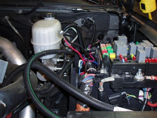
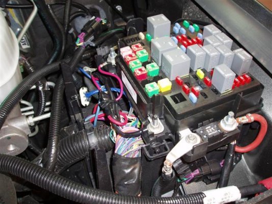
Photo 1 shows the red wire (pin 4 of 7 pin connector on rear bumper), this wire now connects to a black 10ga wire which goes to the first post on the Ammeter. Stud 1 now has the other black 10ga wire going to the second post of the Ammeter.
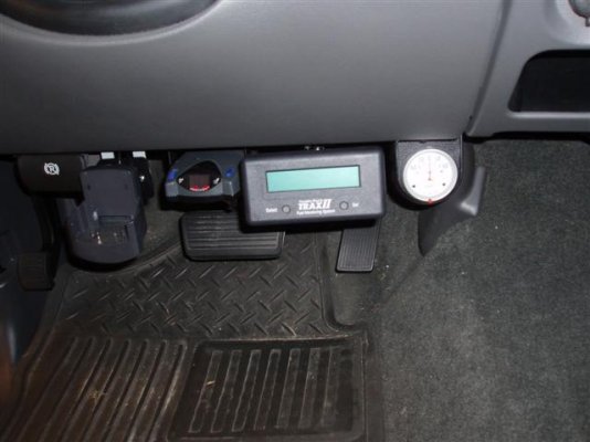
Photo 2 shows the red and black wires taped and tie wrapped to the cable. Photo 3 shows the Ammeter mounted under the dash.
Next I will test the Inverter/air conditioner with the truck attached and post my findings on this thread.
 

Attachments

  • GMC Ammeter 005 (Small).jpg
    GMC Ammeter 005 (Small).jpg
    64.5 KB · Views: 14
  • GMC Ammeter 006 (Small).jpg
    GMC Ammeter 006 (Small).jpg
    76.2 KB · Views: 8
  • GMC Ammeter 007 (Small).jpg
    GMC Ammeter 007 (Small).jpg
    41.1 KB · Views: 11
Back
Top Bottom