zmotorsports
Well-known member
Well, I finally tore into the coach last week to make room for the new residential refrigerator. All in all, it wasn't too bad of a task. Not easy, but not as bad as I thought it would be.
Chrystal and I have talked about installing a residential refrigerator for nearly two years now, waffling back and forth, but our Norcold 1200RLIM has actually done a fair job. We convinced ourselves that we didn't want it to be like the last coach where it went out two days before leaving for a trip and we were scrambling to replace it. We were all set to replace it come next spring before it actually did go out on us. I have heard of many, many people very dissatisfied with theirs, however, ours has actaully performed quite well. That is until the past two trips this year. The first half of the season there were no issues at all, almost had us thinking we were over-reacting, ALMOST.
In July in Salmon, ID and Glacier NP the first three days of the trip it didn't seem like it was working properly but after checking everything over and not having my IR thermometer with me I shut it down for a little bit and turned it back on where it worked fine for the remainder of the trip. It worked very well actually. I didn't give it another thought.
Two week ago we went on our annual trip to Ouray, CO and there again the first half of the week it was not working up to par. I had my IR thermometer and recored temps in the box in the mid to upper-40's. That was it, I told Chrystal when we returned home the Norcold was going out the door, even though I didn't really have a plan yet for the new one.
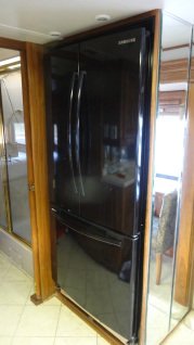
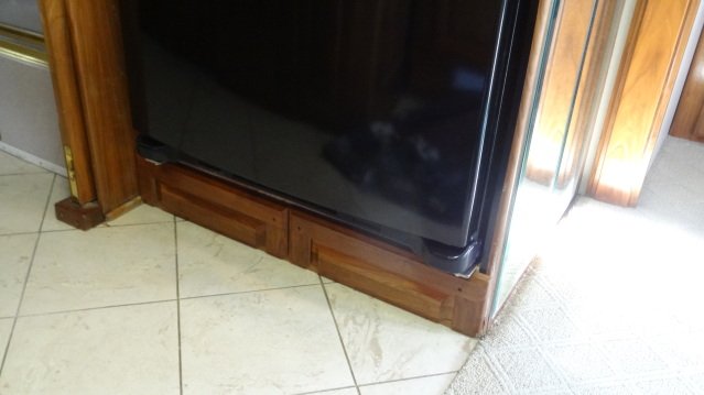
It seems the Samsung RF18 is a popular choice, and for good reason. It is fairly close in physical size to the Norcold but nearly doubling the cubic foot capacity. We went and measured one and Chrystal really liked the model so we purchased one in black. We chose black (or Chrystal chose black) because the microwave and the televisions are black and we (she) thought it would match the walnut woodwork better than stainless steel.
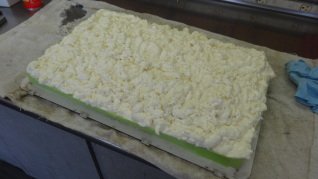
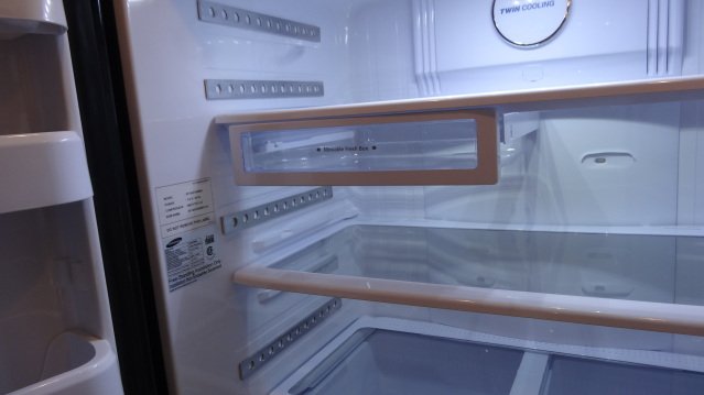
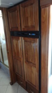
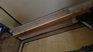
First picture is of our original Norcold prior to being removed.
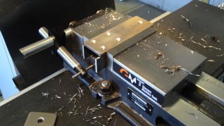
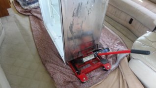
Second picture is of the motorcycle jack/lift we used to roll it out of the way. I was going to build a small cart on casters which is what I saw some other people doing but Jared (our son) had the idea of using the motorcycle jack that was sitting there not being used at the moment.
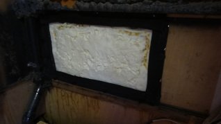
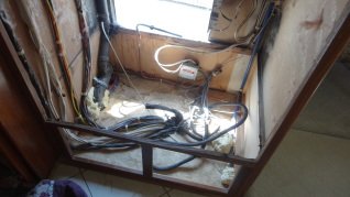
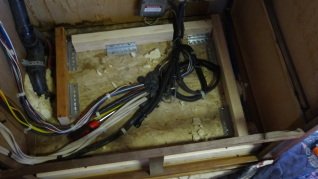
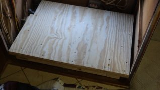
Third picture is of the floor of the cabinet after removing the Norcold, the subfloor and the insulation.
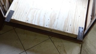
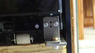
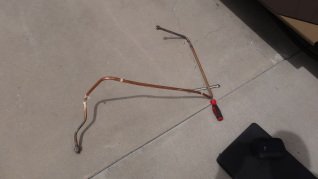
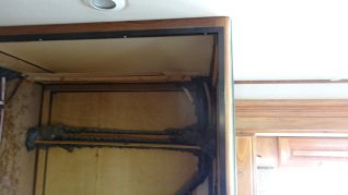
Fourth picture is of the gas line after removal. I was able to gain access to the "T" from the main gas line in the compartment below and remove it as well as cap it off right there.
More pictures in following posts.
Mike.
Chrystal and I have talked about installing a residential refrigerator for nearly two years now, waffling back and forth, but our Norcold 1200RLIM has actually done a fair job. We convinced ourselves that we didn't want it to be like the last coach where it went out two days before leaving for a trip and we were scrambling to replace it. We were all set to replace it come next spring before it actually did go out on us. I have heard of many, many people very dissatisfied with theirs, however, ours has actaully performed quite well. That is until the past two trips this year. The first half of the season there were no issues at all, almost had us thinking we were over-reacting, ALMOST.
In July in Salmon, ID and Glacier NP the first three days of the trip it didn't seem like it was working properly but after checking everything over and not having my IR thermometer with me I shut it down for a little bit and turned it back on where it worked fine for the remainder of the trip. It worked very well actually. I didn't give it another thought.
Two week ago we went on our annual trip to Ouray, CO and there again the first half of the week it was not working up to par. I had my IR thermometer and recored temps in the box in the mid to upper-40's. That was it, I told Chrystal when we returned home the Norcold was going out the door, even though I didn't really have a plan yet for the new one.
It seems the Samsung RF18 is a popular choice, and for good reason. It is fairly close in physical size to the Norcold but nearly doubling the cubic foot capacity. We went and measured one and Chrystal really liked the model so we purchased one in black. We chose black (or Chrystal chose black) because the microwave and the televisions are black and we (she) thought it would match the walnut woodwork better than stainless steel.
First picture is of our original Norcold prior to being removed.
Second picture is of the motorcycle jack/lift we used to roll it out of the way. I was going to build a small cart on casters which is what I saw some other people doing but Jared (our son) had the idea of using the motorcycle jack that was sitting there not being used at the moment.
Third picture is of the floor of the cabinet after removing the Norcold, the subfloor and the insulation.
Fourth picture is of the gas line after removal. I was able to gain access to the "T" from the main gas line in the compartment below and remove it as well as cap it off right there.
More pictures in following posts.
Mike.
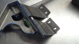
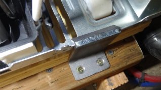
") Trying to figure out a game plan of how to fasten the new fridge to the floor.
Trying to figure out a game plan of how to fasten the new fridge to the floor.