Please help me understand my RV electric

The friendliest place on the web for anyone with an RV or an interest in RVing!
If you have answers, please help by responding to the unanswered posts.
I still do installs on friends cars from time to time so I'll keep the wire and use it where appropriate, better that than waste more $$ in shipping.
 
My 12v ampacity table shows 4 gauge will handle 100A to 12 ft, which is what I am figuring for peak load and distance. My planned load is a max of 6 amps and would rarely run as much as 30 minutes at a time. 2 gauge should give you the extra for 1200 watts continuous.
 
With all this talk about vamps and bolts, I take it that you don't buy into my magic smoke theory.
 
I certainly do, I would like to add automatic transmissions and differentials to the list of things that use magic smoke to operate. In order to work on these things you have to know some special math, people that know the higher maths are called mathamagicians, and that is why some people can fully understand the principles behind magic smoke devices, and repair them without any of the smoke escaping or stop the smoke leaks before it all escapes. The real good ones can actually put the smoke back in.

Bill
 
I still need to know if my theory of operation is correct! Disconnect converter from battery bank when under inverter power? Keep converter connected when in tow OR connected to shore so battery bank gets a trickle charge?
 
I recommend against using the output from the Invertor to power the convertor to charge the batteries.  This is a closed loop and you are creating a situation where the results are diminishing returns.  The conversion of 12 volts to 110 volts or the conversion of 110 volts to 12 volts both have efficiency losses.

You need  to use either shore power, alternator power, generator power or Solar power to charge your batteries.  Using the same batteries to charge the same batteries will always result in losing power and eventually draining the batteries.

This is similar to taking water from one tank, sending it thru leaking pipes and returning it to the original tank.  Eventually the tank will be dry.

You can leave the convertor/charger connected all the time.  However wire or plug it in directly to the A/C source.  It will not cause any problem when you do not have A/C power.

Just do not feed the A/C from the Invertor to power it.  If it is a feed thru it would work but there is no benefit to doing this.

Another thing is that the convertor/charger is almost always much more that a trickle charger.  If your Invertor is also a charger is will not be a problem either.  You can have more than one source of charging at the same time.  As an example most Solar chargers work in parallel with convertor/chargers at potentially the same time.
 
I understand we don't want a loop. So, when 12V+ comes in from the 7 pin tow harness, does it go direct to the battery bank, OR does it route to the converter to piggyback off the converter's 12V charging wire? Would we know if the built in transfer switch in the AIMS 1200 inverter automatically shuts off the 12V to 110V conversion and simply lets the 110V flow through when connected to generator/shore?
 
Odds are the 12v from the tow vehicle goes direct to the batteries, or nearly so. Nothing is going to manage it in any way.

On the inverter, the transfer switch merely selects the 120vac source. As long as shore power voltage is present, it selects that. As soon as the external 120v goes away, it shifts the output load to use the inverter. It's an unknown at this point whether the AIMS inverter mode actually shuts off when shore power is active, or whether the inverter is idling (active but no output load). At least one reviewer claims the latter, which means the inverter would be wasting a bit of 12v power when shore 120v is present. That power is always being replaced by the converter/charger, but it's still a waste.

Some better grade inverters with transfer switches do shut the inverter off, and those that do not typically have a lower idle power consumption than the AIMS unit. It's a cheap design.
 
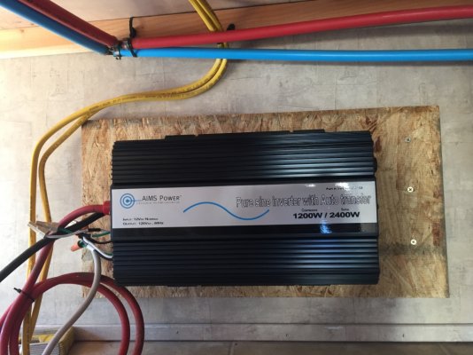
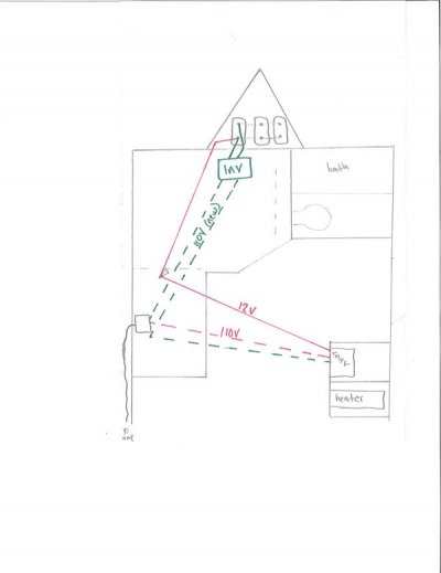
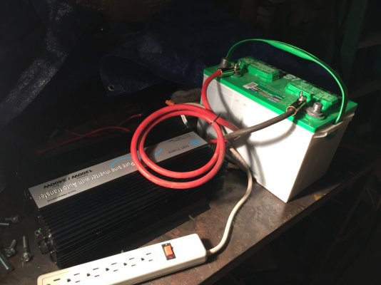
This is how I think I've decided to run the wire. After reading the AIMS install guide, esp the bits about the unit potentially over heating, and the length of the 12V wire run.

If I put the inverter in the compartment behind the converter, I'd need a 12' run of 12V from the batteries, and would need to install an active vent fan on the compartment panel so the inverter and converter do not generate a bunch of heat together. I would also have to run the 12V wires under the cabin since the bathroom is in between the battery bank and the inverter. This would however, make for an easy 110V wire run.

BUT as the installation instructions mention, since 110V is a much higher voltage than 12V, it is better suited for lengthy runs.

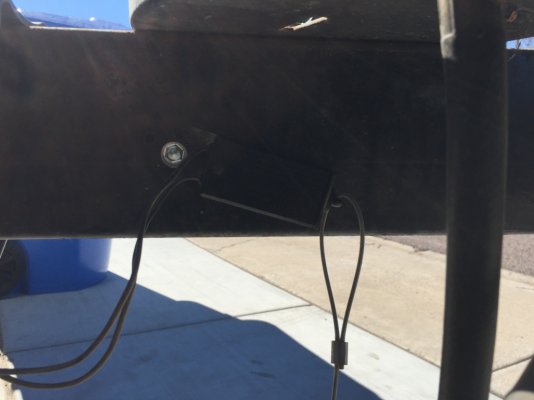
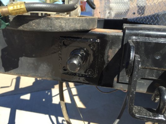
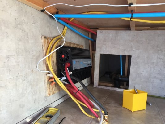
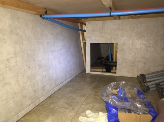
So if instead, I mount the inverter extremely close to the battery bank, in fact on the opposite side of the wall in the crawl space, I can do so with only 2' or so of 12V wire and I can route the 110V through the cabin, entirely in the crawl spaces.

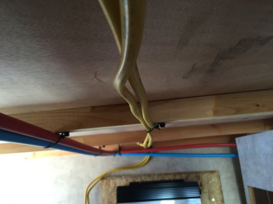
What I'll do is open the electric box where the thick 30 amp cable from shore converts to 3 pull romex, I'll disconnect that union, connect new romex to both and make 2 runs to the inverter.
 

Attachments

  • image.jpeg
    image.jpeg
    28.8 KB · Views: 24
To my surprise all my wire arrived today, the bad review 0ga and the 2ga. Here I compare it to Streetwire 0ga, the welding 2ga, and Monster Cable 4 ga. It's larger than the 2ga by a little so I'm thinking it may be better than the 2ga for this run. It is however, copper coated aluminum whereas the 2ga is pure copper, not sure if that makes much of a difference for a couple foot run.

I also decided to test the inverter while I'm still in a position to return it. Here I'm using only a few inches of 8ga wire and I felt it did pretty good. It went in to protection mode while running a coffee maker and a 500W worklight, as I turned on a second 500W worklight. However it was able to run the (2) 500W worklights by themselves just fine!

Here is a video I shot for you guys!  https://youtu.be/odBtvdhivHM

I think I'll mount it against the interior wall in the crawl space below the front bed, this way it will be a few inches off the floor just in case the crawl space floods. And I think I'll mount the controller to this cabinet, but then again it might be easier to put it in the wall this cabinet is attached to.

EDIT: I noticed the fan stays on, it's 49 degrees outside and there is no load on the inverter. I even hooked up 4ga wires to be sure the 8ga wasn't leaving it starving for juice and its still on. I am going to contact AIMS and see what they have to say about it.
 

Attachments

  • 003.JPG
    003.JPG
    229 KB · Views: 24
  • 004.JPG
    004.JPG
    211.4 KB · Views: 23
  • 010.JPG
    010.JPG
    205.9 KB · Views: 28
  • 005.JPG
    005.JPG
    235.1 KB · Views: 24
  • 009.JPG
    009.JPG
    200.9 KB · Views: 21
  • 011.JPG
    011.JPG
    217.9 KB · Views: 26
I would have some serious reservations about using aluminum wire.  There is the corrosion factor and the fact that it does not stand up to vibration near as well as copper.
 
A couple of the Amazon reviews mentioned that the fan on the AIMS seems to never shuts off when the inverter is running, which would refute the claim that the fan is thermostatically controlled.  It IS supposed to shut off when the transfer switch engages, however. Did you test that?
 
I have not tested the ac power pass through yet. I did email AIMS tech support and I'm curious as to what they say. Something tells me though, this inverter relatively new to the market, and at this price point, they're conducting research and collecting feedback from buyers. This could be a small manufacturer's glitch they are considering fixing. That or updating the manual ;)
 
More likely it is a product shortcoming and they are selling off inventory prior to replacing the model with an improved design. Another site that sells this particular model mentioned a limited time availability.
 
I worked my tail off today. Re-installed one side of the bed rails then pulled the other, primered and painted it. Then I decided to weld the new, front leveling jacks and the new extra anti-sway ball to the trailer frame. Cleaned and hit those with paint once they cooled. I also relocated the trailer's emergency brake switch since it was in the way of the anti-sway ball.

Then I decided to get in to the inverter project. I installed a mounting board then put it on. I ran the 110V and remote wire, fishing the remote wire up the wall and flush mounted the inverter remote in the TV cabinet space.

As for Gary's question about the 110V pass through I confirmed the bad news, the inverter has to be ON to pass it through. The cooling fan did shut off for this but I need to find out the current draw while in this mode.

I also found out that 3 group 27 batteries in their boxes are NOT going to fit easily on the tongue behind the propane tanks. I'm not very happy about that but I am on the fence whether to buy 2 more of these acid bath Interstates, or buy 3 AGMs.... I'm considering the AGMs due to not boiling and emitting gas while charging so I could store them right by the inverter, saving the need to drill through the floor of the cabin.
 

Attachments

  • rv1.jpg
    rv1.jpg
    307.8 KB · Views: 19
  • rv2.jpg
    rv2.jpg
    241.9 KB · Views: 20
  • rv3.jpg
    rv3.jpg
    301.3 KB · Views: 18
  • rv4.jpg
    rv4.jpg
    306.7 KB · Views: 17
  • rv5.jpg
    rv5.jpg
    182.4 KB · Views: 15
  • rv6.jpg
    rv6.jpg
    280.2 KB · Views: 16
  • rv7.jpg
    rv7.jpg
    187 KB · Views: 17
  • rv8.jpg
    rv8.jpg
    293 KB · Views: 17
  • rv9.jpg
    rv9.jpg
    269.5 KB · Views: 24
  • rv10.jpg
    rv10.jpg
    208.8 KB · Views: 22
  • rv11.jpg
    rv11.jpg
    316.9 KB · Views: 19
  • rv12.jpg
    rv12.jpg
    215 KB · Views: 19
Thanks for confirming the pass-through mode "on" requirement. That's really a poor design, but the price of the unit makes it worth putting up with. And a DPDT switch could always be added to manually bypass the inverter when staying longer term with shore power. A 20A DPDT switch isn't expensive and will do duty as a manual transfer switch.
 
I tried to find one of those switches for a different project and couldn't find one. Could you please post a link to one? Maybe an idea of how to wire it as well?

I have some concerns about the trailer harness wiring though. I read a lot of info in the Library including the bit on purchasing a used trailer and what to look for. I know the trailer brakes work as I had to slam on truck brakes in July and the trailer locked up too. But I read about testing the emergency brakes and I pulled the pin with the truck connected to the trailer and I heard nothing. I also noticed I am not getting 12V out from the truck. I tested fuses and one of the "TRLR" fuses was blown, I replaced but that did not change anything.
 

Latest posts

Members online

Forum statistics

Threads
131,972
Posts
1,388,449
Members
137,722
Latest member
RoyL57
Back
Top Bottom