Please help me understand my RV electric

The friendliest place on the web for anyone with an RV or an interest in RVing!
If you have answers, please help by responding to the unanswered posts.
Here is one on Amazon:
http://www.amazon.com/Heavy-Duty-Toggle-Switch-Center/dp/B001FRE1E8
http://www.amazon.com/gp/product/B00004WLKA/ref=pd_lpo_sbs_dp_ss_1?pf_rd_p=1944687602&pf_rd_s=lpo-top-stripe-1&pf_rd_t=201&pf_rd_i=B001FRE1E8&pf_rd_m=ATVPDKIKX0DER&pf_rd_r=0BWH1W9D9B0QJ5XMWAE2

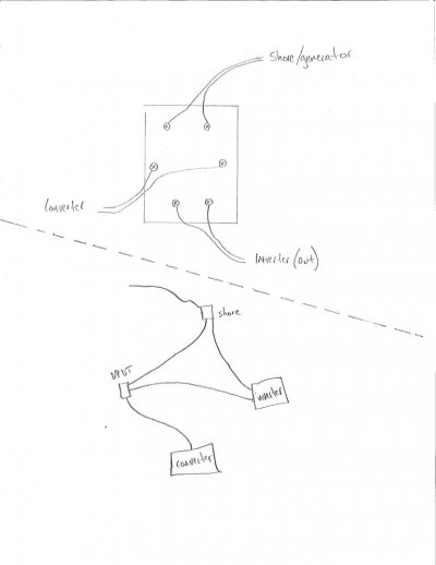
Wire the output of the switch (the "center" terminals) to the load, one input terminal set to the 120v line source, and the other input to the inverter output line.  When you put the switch  to the Line side, you have a direct path from 120v line to the load (wall outlet or whatever you are powering), thus bypassing the inverter altogether. When you flip it to the inverter input side, the line power is removed from the load and the load receives power from the inverter line instead. It doesn't matter if the 120v line is hardwired to the inverter and hot, or if the inverter remains on, cause the inverter output line is terminated at the DPDT switch unless it is in the inverter-feed position.

Since it is double pole, both the hot & neutral get switched. Ground is not a concern - they all ultimately are common anyway (connected to the RV chassis at inverter and at line load center).

The above switch has a "dead center", but that is not necessary. You can use one without that feature just as well.
 
Thank you, and here is my video where I test the transfer switch. I set my phone in the freezer, had it monitor the remote while on battery power while I walked out and connected my 30amp service.

https://youtu.be/SNa8EiADkKo

On that switch, since its 20 amp only, would it cause a problem when connected to shore power, running the A/C, etc at 30amps?
 
Please tell me if this is how I would wire the switch. And since drawing it, it seems obvious I need a 30 amp DPDT? http://amzn.com/B00N7GJNK2

What about a 30amp DPDT relay to make the switching automatic? http://amzn.com/B000JJM7ZS

And $hit, should I have run 10ga 110V instead of 12ga to the inverter since it's a 30amp system?
EDIT: maybe not since the inverter will NEVER run the A/C, however, when I make the run from the shore/generator to the DPDT, I have the opportunity to make that 10ga since that's where the A/C would pass through?
 

Attachments

  • image.jpeg
    image.jpeg
    38.4 KB · Views: 20
On that switch, since its 20 amp only, would it cause a problem when connected to shore power, running the A/C, etc at 30amps?
Yes, it would overheat. The switch has to be rated the same as the line circuit that runs through it. If placed in a 30A circuit, it needs to be 30A. The inverter peak, though, is 20A (2400 watts), including via its internal transfer switch. You should not plan on running 30A through the inverter in pass-through mode.
 
I'm not clear on why the switch output (load) side goes to the converter. Or is that intended to represent the entire 120v load center (breaker box). Merely powering the converter alone just gives you 12v power, and you don't need the inverter for that at all. In fact, you do not want the converter itself powered via the inverter, since it will attempt to charge the batteries!  You would be drawing power from the batteries via the inverter and trying to put it back in via the converter.

Are you trying to power the whole RV from the inverter?
 
I'm really glad all this info came up, I didn't even realize I was running ALL the 110v through the inverter as I was installing it, probably wouldn't have been an issue until summer when I would've gone to run the A/C and burned up the inverter pass through feature.

So I believe the 30amp DPDT switch will allow me to bypass the inverter completely using all 10ga wiring. I think the 30amp relay is pretty cool BUT I think for this application, I want to be in control of what is powering as opposed to having an automatic "switch". I hate to pay $75 for a 30amp DPDT when the 20amp is less than $8 but that's life I guess. I plan to install it next to the inverter remote in the cabinet, in an old work gang box.

I am NOT trying to power the entire rig off the inverter, just the outlets, TV, phone chargers, LED night lights, etc, and wishfully the microwave. I realize the AIMS 1200 inverter may not be enough for the microwave that is in the RV, but maybe a more modern, more efficient one would- I'll have to look at specs and prices.

I thought this was the proper way to install the inverter and I asked earlier about the routine I would need to follow of disengaging the push/pull switch so that the inverter doesn't power the converter to charge the batteries. What other way would you install it? I do not want to wire a dedicated outlet, I'd prefer to have all except the A/C powered.

I've learned a lot here with your help and I thank you guys sincerely for that.
 
I'm still not clear on what you are connecting the inverter output to. For example, if you plug the RV shore cord to it, then of course everything can run that way. But if you connect it to just one or two outlets or branch circuits, then only those get powered.    You showed it going to the "converter", but in your rig the converter is part of the main AC/DC load center, so I asked the question.

The best, but most difficult, installation is to isolate the desired circuits via a secondary power panel and power only that from the inverter. If you try to power the main load center via inverter, you must be very careful to avoid having the converter/charger run, or the a/c or any other large power draw (e.g. fridge or water heater in a/c mode).  You also have the problem of running a high amp device when the inverter is in pass-through mode. That includes the aforementioned, as well as things like a space heater or electric fry pan.

If you decide to arrange a bypass, make very sure there is no way the inverter can ever send power to the load center (or any branch circuit) at the same time as shore power. Lots of sparks will fly and all the smoke will come out if that ever happens, even for a moment. Do not rely on remembering to flip a switch off first, cause sooner or later you will forget.
 
When you look at my image in Reply #82, isn't it impossible to power the converter with shore and inverter at the same time? Doesn't the DPDT switch isolate the sources and limits only to only one at a time? Yes it does create potential to inadvertently attempt to turn on the A/C while in inverter pass-thru mode but wouldn't that simply send the inverter in to protection?

What are your thoughts on this write up from http://www.doityourselfrv.com/rv-inverter-install-diy  ?

RV Inverter Installation Method 4.

rv-inverter-install-30-amp

A good compromise is to install a 30 amp receptacleon the outside of your RV and then connect it to the output of the RV  inverter. When you want inverter power, you just unplug the RV from shore power and plug it into the new 30 amp receptacle. With one modification, this is how my current RV is set up.

You recall that the converter and inverter should never both be on at the same time? No problem. I just flipped the circuit breaker for the converter before turning on the inverter. That is, until the time I forgot to flip it, and went to bed. I got up in a hurry when the low battery alarm on the smoke detector started beeping at me.

The reality is it should have been idiot proof. The solution is to get a relay (an electrically operated switch) with a 120 VAC coil and normally closed (n.c.) contacts that are rated at least 10 amp, DC. The figure below shows how to wire it. Connect the relay coil to the inverter output. Then disconnect the hot supply line from the converter and reconnect it through the n.c. relay contacts. Now, when the inverter is turned on or off, the relay automatically switches the converter off or on.


It will be most convenient to mount the relay on or close to the converter. Because the relay coil draws only a very small amount of current, you can use 18 AWG (lamp cord), or cut up a heavy duty outdoor extension cord if it needs physical protection. If your relay has any additional contacts, just ignore them.
 
You may not have noticed my byline on that DIYRV article.  ;)

I did not write the original, but I corrected some problems with it and thus became the author of record for it. I have some other articles on DIYRV.com as well.
 
When you look at my image in Reply #82, isn't it impossible to power the converter with shore and inverter at the same time? Doesn't the DPDT switch isolate the sources and limits only to only one at a time?

Yes, but you keep missing my point. You aren't powering only the converter from either source.  You are powering the entire AC/DC load center. You need a way to avoid allowing the converter to run along with everything else (does it have a circuit breaker of its own?). And it would be smart to do the same for water heater & fridge electric & a/c units. Flipping their breakers off, if they have separate ones, may be sufficient.

OK, now suppose you have the inverter enabled and the manual switch in inverter position. Now some helpful person comes along and plugs your shore cord into a nearby outlet. What happens?  Is that DPDT switch between the shore cord and the load center? Or on some alternate path you have created when the inverter is added? I can't tell, cause you never described the rest of the 120v hook-up.  I'm not saying its wrong, just warning you that it is absolutely critical to isolate the two system.
 
Yeah there is something I am missing here. What is wrong with the inverter powering the entire AC/DC load center? (as long as I'm not using it to recharge the battery bank and not trying to run the A/C) I agree it's redundant and probably inefficient to have 12V batteries supplying power to the inverter supplying power to the converter, converting the 110V back to 12V for things like the refrig, heater, etc BUT I'm baffled where to hook the inverter in to avoid all this.

So the friend comes and plugs in the shore while DPDT switch has converter running on inverter mode, I'm relying on the inverter auto transfer switch to pass through the shore power.

To be honest I felt I had shown you the entire 110V system, no I did not illustrate the A/C unit or the multiple wall outlets but that's all she wrote. The system in my rig is pretty simple.
 
That "loss of efficiency" is a major one. This inverter loses more than 10% of the input power when inverting, and then you lose another 5-10% converting back for charging at the converter. And that continuously increases as the batteries run down and the charger raises its output to try to keep up.  Very shortly both inverter and converter/charger are running at max and the batteries die.

As for powering the rest of the circuits, do what you feel is best.
 
Gary, without a question you've been a huge help but I think we're both missing each other here. I absolutely will not have the converter charging the batteries while on inverter power. There will be no connection between the converter and the battery bank while under inverter power. That will be a manual task of pushing in the push/pull switch but I plan to laminate a hard card of instructions and keep a copy by the controls and by the inverter so simple my young children could follow.

So, knowing that I will not create a loop of battery bank > inverter > converter > battery bank, are there any other concerns?
 
Does the shore power cord connect to the AC input of the inverter?  I would not do that, due to overload concerns. Or I would put a 20A circuit breaker in line with it, to make sure I didn't overload the inverter transfer switch.

Over the years we have seen many electrical problem reports here, and too often they begin with "I forget to...". That makes me inclined to want electrical things to be foolproof. I'm a firm believer in Murphy's Law: "If anything can go wrong, it will!".
 
Here you can see how I did wire the inverter to the 30amp shore service. I know I need to install a cable clamp but I'm still in 'figuring it all out' mode.

I happen to have a spare sub panel type of box and 20amp breaker!

I'm happy to put that in line TO the inverter.

Maybe I'm starting to over complicate things but I'm thinking a DPDT switch on the 12V converter input might be a good idea. My thought here is that I could run the 12V appliances (heater, water pump, etc) DIRECT from the battery bank and the inverter only powers the converter's 2 15amp breakers which represent the outlets.
 

Attachments

  • 002.JPG
    002.JPG
    244.6 KB · Views: 43
  • 001.JPG
    001.JPG
    325.5 KB · Views: 40
I just sketched this, maybe it is helpful?

But I'm confused on how the converter actually works. Well maybe not, all of the 12V appliances actually do run direct off the batteries correct? Then, the blue wire (CONV POS) must connect to the BATT POS through the circuit board which charges the batteries?

You can see my converter in Reply #1
 

Attachments

  • image.jpeg
    image.jpeg
    49.2 KB · Views: 36
To simplify, I want the battery bank to continue to power the 12V appliances DIRECTLY.

I want the inverter to ONLY power the 2 15amp breakers in the panel.
 
I get confused when you say "converter" but appear to mean the more than that, e.g. 120v breakers. The converter/charger is the component that accepts 120vac and produces 12-14vdc to supply coach coach power needs and charge batteries. That's all it does.

You appear to have an integrated power center that has at least these three major components:
A. 120v power bus with 120v breakers
B. Converter/Charger
C. 12v Power bus with fuses

Your 12v appliances are wired to the 12v bus and the bus receives power from both batteries and converter/charger. I can't tell from the pictures exactly how the two power sources get there, nor can I tell what brand of power center you have. The converter produces power when it has 120v input but is dormant otherwise.  There should be a circuit breaker on the 120v side for it, but that breaker may be shared with other 120v devices.  If it does not have its own breaker, you could add a simple on/off switch to the internal wiring to turn off power to the converter component alone.

Your shore power cord connects to the 120v bus which in turn feeds the 120v circuit breakers. I can't tell from the photos how the inverter fits in - it could be in series with the shore cord, or in parallel with it.  I'm guessing you chose series, i.e. the shore cord sends power through the inverter and relies on its transfer switch & output wire to send it back. If so, that means 30A flowing through a device designed for 20A, thus the suggestion to put some kind of 20A limiter in it. But that limits ALL your power to 20A, even when not inverting.  To get around that, you can put a 30A DPDT switch (aka "transfer switch) between the inverter 120v input and output and manually bypass the inverter when you are using 30A shore power alone.

The alternative to the series hook-up is to place the inverter in parallel with the shore cord and have both feed the 120v bus. HOWEVER, that means you MUST add a transfer switch to make sure the two are never active at the same time. The 30A DPDT switch can be used to do that manually, or for more $$ you can install an automatic 30A transfer switch that senses shore power and switches accordingly. The DIYRV article addresses that design.
 
The converter is a Parallax Model 7345 and has those 3 major components. Currently the inverter is in series with the 30 amp shore as you describe it. This is not an issue for Yosemite but one I'll need to figure out before the summer.

I ordered the Hubbell manual switch and the darn shipping is 4-7 WEEKS- bummer. I'm thinking I could order this relay and set it up as my automatic transfer switch. It seems from the reviews that is exactly what people are doing with it. I would need some guidance wiring it in though.

I think as well, if I put a switch on the blue CONV POS line, that would be a more efficient way to break the loop. Again, this would be a manual procedure but tends to make the most sense IMO.
 

Latest posts

Forum statistics

Threads
131,974
Posts
1,388,531
Members
137,723
Latest member
CarlSpackler
Back
Top Bottom