RV Products - Power Control Center Fuse ID

The friendliest place on the web for anyone with an RV or an interest in RVing!
If you have answers, please help by responding to the unanswered posts.

dalet

Active member
Joined
Apr 2, 2016
Posts
43
Location
San Diego
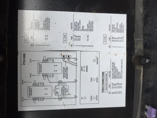
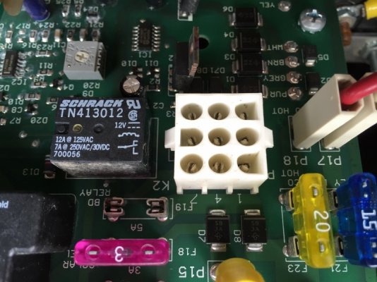
I have a 3amp fuse in my RV Products CB115 (rev j) Power Control Center (PCC) that keeps blowing the second I plug the new fuse in.  The fuse is labeled "F19" and "BD Relay" , and the schematic on the door is dual labeled that "F19" is for both the "Coach BD Power" and "Chassis BD Power".  I assume "BD" stands for Battery Disconnect, but what could a 3amp fuse be protecting?

I looked through the pile of owners manuals that came with my coach when I bought it, but could not find a BCC owners manual, and the web was not much help either.  Hopefully, someone on this forum steer me in the right direction, or ID the component that would be blowing a 3amp fuse.

FYI... I posted a problem regarding my inverter dying on "The RV Forum Community ? RVing message boards ? Tech Talk ? Inverter Problems" and wonder if these two problems are related?

Thank You in advance for any help.
 
A relay, i.e. the Battery Disconnect, works by placing a small current across two terminals that power an electro-magnet, which in turn moves a big switch that handles the battery cable current. At a guess, that relay is bad, e.g. the electro-magnet shorted. Could be the wires to it as well, though. I believe you will find that BD relay right on the RVP board. Or two of them (house and chassis).

The RVP BCC diagram I have shows F19 as 7.5A, but it maybe an older or different version than what you have.
 
F19 was changed from 7.5A to a 5A fuse on Release "J" of the CB-115.
 
The fuse feeds power to the Disconnect Switches located over your entry door.  It's possible one of those switches has a power lead shorted to ground.

You might try toggling those switches several times to clear the condition.  If that doesn't help, you could unplug connector "P2" from the board, and check for continuity between "Pin-9" on the cable portion of the connector, and each of the other "Pins".  There should be no continuity between any of the "Pins" on that connector.

If that proves OKAY, I suspect the "Electronic Disconnect Module" on the CB-115 board.

Just For Information - The only purpose of the Electronic Disconnect Module is simply to turn ON the disconnects when the Ignition is turned ON.  This is to eliminate some cursing (and the need to get up from the drivers seat) when you try to start the engine and discover that you forgot to turn the batteries ON.  :D
 
Thank you for the responses.  I will do some checking and get back to you. 

And to Just Lou response... my battery disconnect switches over my door have been intermittent lately and are not disconnecting or reconnecting the batteries?  Could be that the actual relay on the PCC board is bad, or the switches are faulty. Sounds like trouble shooting is ahead. 

Again, thank you!

Dale
 
After further review I pulled the P2 plug and found that pin 9 has continuity between pins 7 and 8 on the circuit board side. While this plug was disconnected I pulled the 9 pin plug off the actual battery disconnect switches over my coach door and checked continuity, and found no continuity there. This ruled out a shorted wire (i guess). 

The schematic shows that pin 7 and 8 power the Coach Battery disconnect switch (relay?), and shows that pin 8 is also connected to the Aux start relay so I activated the yellow wire with my Power Probe, and the relay responded with a solid click. Just for grins in reinstalled a new 3amp fuse and it blew immediately

So, am I safe to assume that the Coach Battery Disconnect switch is shorted and needs replacing?

Thank You
 

Attachments

  • IMG_6147 (600x800).jpg
    IMG_6147 (600x800).jpg
    230.4 KB · Views: 23
  • IMG_6142 (800x600).jpg
    IMG_6142 (800x600).jpg
    252.4 KB · Views: 23
I'm a little confused. You say that the F19 that is blowing is 3 amp, yet the board is clearly labeled that the fuse should be a 5A fuse. Have you tried a 5A fuse in the F19 slot?

 
dalet said:
After further review I pulled the P2 plug and found that pin 9 has continuity between pins 7 and 8 on the circuit board side. While this plug was disconnected I pulled the 9 pin plug off the actual battery disconnect switches over my coach door and checked continuity, and found no continuity there. This ruled out a shorted wire (i guess). 

The schematic shows that pin 7 and 8 power the Coach Battery disconnect switch (relay?), and shows that pin 8 is also connected to the Aux start relay so I activated the yellow wire with my Power Probe, and the relay responded with a solid click. Just for grins in reinstalled a new 3amp fuse and it blew immediately

So, am I safe to assume that the Coach Battery Disconnect switch is shorted and needs replacing? Thank You
Where to start ??

Fuse F-19 has been 7.5A and 5A at various times in the evolution of the CB-115 board.  The introduction of (and design variations of) the electronic disconnect relay driver required different current capabilities over the years.  Use the size fuse that your board calls for.

Your Disconnect solenoids (relays) are NOT shorted.
Your Disconnect switches are NOT shorted.

In my prior post, I was referring to measuring between pins on the CABLE connector, which goes to the external BD switches.  There should be NO continuity (shorts) between any of these pins if the switches are not defective.

However, continuity between pins 7 and 8 (on the board side) is normal.  This is, in fact, how the switches get their battery voltage to activate/deactivate their respective disconnect solenoids.  Continuity between pins 7/8 and pin-9 is not normal, however.  Pin 9, on the board is hardwired to ground.

So, the continuity between pins 7 & 8 and pin 9 (on the board) is causing your fuse to blow.  It indicates that pins 7 & 8 are shorted to ground, somewhere on the board.

I'm going to give you a link to a more detailed schematic (diagram) of the BCC, so you can see how these things all work together.  Read the entire document for a clearer understanding of how it all works, and how to troubleshoot future problems.

My guess is that the short to ground is associated with the "Ignition Lock Out" relay on the board.

You will see the P2 connector on the left side of the (figure-2) diagram.  There is not much distance or circuitry between the connector and the fuse.  Pins 7 goes directly to the f-19 fuse, but pin 8 passes thru the lock out relay contacts on the way to the fuse.  The short to ground is somewhere in that path. 

 
Just Lou - Thank you for the troubleshooting guide. After reading it I better understand the PCC and its functions.

The original fuse was a 3amp so I went with it, and now notice that the board says 5amp. The 5amp blows just as fast though, so I will look in to the "Ignition Lockout Relay" when I get a chance this week.


its been a while since my last post, but i took Lou's advice and found that the ignition cutout relay was fused together.  i ordered a new board from fleetwood and all is well.  Thank you Lou for your patience and sound advice.
 
dalet said:
its been a while since my last post, but i took Lou's advice and found that the ignition cutout relay was fused together.  i ordered a new board from fleetwood and all is well.  Thank you Lou for your patience and sound advice.
Glad it's fixed.

You might want to hang on to that old board, as it's fairly simple to replace that relay.  The board may have some value to you if listed for sale on this forum, Craig's list or ebay.  You might be able to help someone else with BCC problems, and recoup some of your costs at the same time.  Just a thought.
 
This is just an observation--I don't know if it's an important observation, but although the board says F-19 should be 5 amps, it looks to me like the schematic shows that F-19 is 3 amps.  If you turn the image right-side up, this is what I see in the writing near the upper right corner of the schematic.
 
richardhufford said:
This is just an observation--I don't know if it's an important observation, but although the board says F-19 should be 5 amps, it looks to me like the schematic shows that F-19 is 3 amps.  If you turn the image right-side up, this is what I see in the writing near the upper right corner of the schematic.
It depends on the release level of the board just what amperage F-19 should be.  The schematic (in the official RV-CP document) tries to show the latest level.  The load on that circuit underwent several changes over the years due to the design/re-design of the disconnect relay driver circuitry.  F-19 has been 3A, 7.5A and 5A at various times in the evolution of the CB-115 PC Board.

The charts and basic diagrams on the box cover don't always agree with the actual board installed.  The best advice is to use the level fuse called for on your particular board.
 
the new CB115 rev P board came fully loaded with fuses and circuit breakers.  the F19 has a 5 amp breaker, which implies that it is still problemamtic 
 
dalet said:
the new CB115 rev P board came fully loaded with fuses and circuit breakers.  the F19 has a 5 amp breaker, which implies that it is still problemamtic
I'm not sure that indicates anything problematic.  I've got a level A board that has worked without error for 19 years.  Go enjoy the RV.
 
Back
Top Bottom