Inverter/Converter issue

The friendliest place on the web for anyone with an RV or an interest in RVing!
If you have answers, please help by responding to the unanswered posts.

The_Grey_Wolf

Active member
Joined
Jun 8, 2016
Posts
29
Location
New England
Help!

I bought a new 2015 Grey Wolf 23DBH last year.  I put a battery bank, and 3000 watt inverter/charger with built in relay in it.  Everything has worked great until this week.  When I installed it, I "permanently" switched the converter breaker to off to avoid the battery charging loop.

Fast forward to last Sunday when my son put it on because he thought it would put the tv on. It stayed on for a couple of days and took my battery bank down to 0. I have recharged the batteries and I'm running a desulfate to repair the battery damage.  However, now that I have the inverter running off of shore power, all of the AC power items are running fine, but nothing DC is running unless I put the converter on.  Any ideas?

I replaced the 15amp breaker, but that didn't help.
 
If I understand you correctly: the batteries have finished the desulfate cycle - the converter does provide 12V properly - but no 12V power when using only the batteries.

Is there an in-line fuse between the converter/charger and the batteries?  Do you have an ON/OFF switch at the batts?  Also, how do you isolate the inverter and converter?
 
I'm guessing that the "converter" in this story is the original one on the trailer, and that the new inverter/charger is separate from it? In other words, your RV now has tow converter/chargers and you keep the original (non-inverter) switched off.  Is that original converter/charger also contain the 12v power bus (where the 12v fuses are)? Or is that separate? If not sure, can you give the make & model of that original converter/charger? I ask all this because I'm trying to get a mental picture of how your 12v system is wired and powered.

Basically you had batteries and the original converter/charger in parallel and now have added another inverter/converter/charger in parallel with the original set-up. Any of the three ought to be able to provide 12v when shore power is active, but you seem to be getting it only from the original converter. That suggests both the batteries and the new inverter/charger are offline, so the way they are all wired together is the key factor.
 
Batteries have finished and are now holding steady at 12.7. 

The battery bank is supplying AC power just fine when there is no shore power.  However, none of the DC components will work.

To answer your questions:

Yes, there is a 500 amp ANL fuse between the battery bank and the inverter.  That is intact.  The marine grade battery cutoff switch is on.

The converter has always been disabled at the breaker.  My son flipped the breaker on and it took the batteries down to 0.  I'm lucky they're ok actually. 

I'm just confused at why all of a sudden the DC side won't run without the converter. I'm thinking there has to be something wrong with the wiring coming out of the batteries to the DC junction box, but all looks good and was working as of last week.
 
Hi Gary,

The converter is original, but has never been used. I don't even know the make and model. It's an open face converter and looks dirt cheap.

The 12 volt system has never been modified.  The original wiring is in place, the only thing I modified was adding the inverter. The inverter has a relay built in and a charger, so the converter was rendered useless.

It's almost like the 12 volt system all of a sudden feels it isn't grounded unless the converter is on, but nothing has changed since it worked last week. 

 
Strange indeed. Something must have failed when the batteries went dead, but I'm struggling to guess what it might be.

When using the inverter without shore power, do you also have 12v?
 
I do not have DC power on shore or battery/inverter without the converter running.  I'm really leaning towards a DC ground fault since the converter has its own ground.  I just can't figure out what has changed.
 
Yet the inverter has to have a battery ground connection to work, so there has to be a functioning ground path.

I'm not sure what you mean by an "open face" converter and you did not answer the question about the location of the 12v distribution panel (bus bar and fuses). The problem is loss of hot or ground to the 12v power bus when the converter is not on. Battery power isn't reaching it and the only power there is coming from the original converter. You need to be looking at the path from battery and new inverter to that 12v bus/panel and find what is broken in between. Both of those have to be able to send 12v power to the 12v bus/panel and they are not doing so.
 
Sorry Gary, the 12v bus is located next to the fuse panel underneath the fridge.

What I mean by open face converter is that there's no enclosure like you would see with a nice parallax.  It's just a board with an aluminum flap.  It looks cheap and I'm glad it is not charging my Trojans.

I'm going to go point by point from the batteries to the bus panel, but again, this worked last week without any changes.  Something happened with that converter on, maybe something fried in the DC line, maybe excessive heat, I'm not sure, but I'll look.
 
So DC power is making it from the converter to the DC buss bar but no power is making it from the batts to the DC buss bar.

Check your ground connection for the batteries, check for a short in either + or - wires coming off of the batts and pull the marine switch off and double check the back of the switch.  I have seen switches fried at the connections on boats.
 
The easiest way to narrow down the possible issues is to disconnect the POS wire at the batt and run a jumper wire directly to the 12V buss bar from the batt.  If you have power, the issue is in the POS side wiring.  If you don't, start your tracing on the NEG side which is still connected at the batt.
 
The NEW...
The new inverter/charger is hooked directly to the batteries through that 500amp ANL fuse.  That path will allow the charger portion of the I/C to charge the batteries, and also provide a path from the batteries back to the I/C to operate the inverter.

All this appears to be working...  (your batteries were recharged via this path, and the inverter works)

The OLD...
The converter is hooked to the DC distribution panel and DC BUS.  The batteries are connected to the BUS (and thus to the converter and distribution panel) through a previously existing path.  This is how the converter USED to charge the batteries, and how battery power returns to the bus when not plugged into 120vac.

This path is NOT working.  The converter is powering the BUS, but the path to/from the batteries in now OPEN.

That old converter may have two outputs (one to the bus and one to the batteries.)  Check that later one.

It is not unusual for there to be a fuse or breaker in the path, back to the converter from the batteries, as well as protection at the converter end.

By the way - your new I/C expects the path from the batteries back to the BUS (distribution panel) to remain intact, since it does not establish that path simply by being connected to the batteries.  In other words, DC does not travel backwards through the I/C to do anything but power the inverter.

Hope this helps. lou
 
Ok here are my findings...

I used my voltmeter with both the shore power in and then inverter power. There is nothing coming to the bus without the converter on in either situation.

So I traced the DC power to this thing called a 30A, 24V Shortstop. All my DC components hook to this.  As far as I can tell there is no damage to it, but it's tucked away nicely behind the tongue. My voltmeter shows power going to the shortstop. As far as I can tell from the POS line out there is power when I place the voltmeter in the line out to the bus.

I keep returning to there being a ground fault somewhere at the BUS from the I/C but I can't find one. All grounds look good.  I just can't figure out why the converter would run the bus. I will review all comments again and see if a lightbulb goes off.

Im at a loss here. Everything is powered except the bus.
 
Did you run a new line from the battery's POS post directly to the POS buss bar (put an in-line fuse in the line) ?  If you still do not have power and the fuse does not burn, there is a 99% chance it is in the NEG side.  That is the easiest way to determine which side your problem is on.

ETA... did you ever mention if your RV is 30 or 50 amp?
 
The_Grey_Wolf said:
Lou,

The DC panel and bus has a direct path back to the batteries, not from the converter.  Would pictures help?
I agree that is what should be.  The question is, does that path have continuity from end to end?

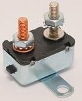
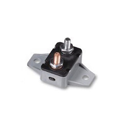
By the way - that thing called a "shortstop" is actually a circuit breaker.  Most of them will have a small black plunger in the base to reset it if it is tripped.  (see the attached) Your symptoms are pointing clearly to that path from the batteries back to the bus/converter.

Your batteries will test good, because they are being charged from the charger in the I/C via the 500amp fuse.  The converter is feeding the BUS, as it should, because there is no battery power back to the BUS.
 

Attachments

  • manual reset CB.jpg
    manual reset CB.jpg
    3.8 KB · Views: 3
  • DC CB Manual.jpg
    DC CB Manual.jpg
    8.2 KB · Views: 3
Yes, a picture of the DC distribution panel and the converter section would help.  The make and model of the panel and converter would also help. 

The problem could very well be on that end, if the circuit breaker proves to NOT be tripped.

Like I said in an eaqrlier reply, some converters have two outputs, one for feeding the bus and another to connect to the batteries for charging.  The batteries are effectively disconnected from the bus when the converter is active.  A bad relay contact could prevent the battery from re-connecting to the bus.  Knowing the make and model would help establish this as a probable cause.
 
More pics will have to wait for light as the camper is pitch black.

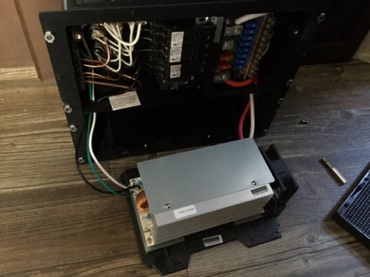
Here's the converter. There's one line to the panel. However, there's a separate line to the batteries from the panel that I'll snap a photo of tomorrow. The wiring diagram is tiny, or I'd include that.
 

Attachments

  • image.jpeg
    image.jpeg
    111 KB · Views: 16
Just Lou said:
Yes, a picture of the DC distribution panel and the converter section would help.  The make and model of the panel and converter would also help. 

The problem could very well be on that end, if the circuit breaker proves to NOT be tripped.

Like I said in an eaqrlier reply, some converters have two outputs, one for feeding the bus and another to connect to the batteries for charging.  The batteries are effectively disconnected from the bus when the converter is active.  A bad relay contact could prevent the battery from re-connecting to the bus.  Knowing the make and model would help establish this as a probable cause.

Just Lou...he stated in an earlier post "The DC panel and bus has a direct path back to the batteries, not from the converter".
IF that is correct, not sure how the converter could effectively disconnect the batts from the buss?
 
Back
Top Bottom