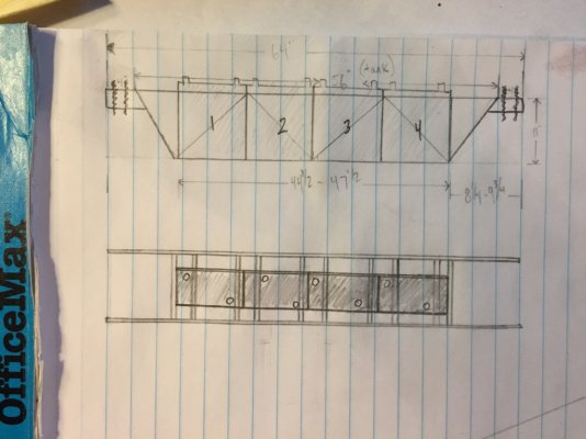
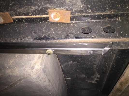
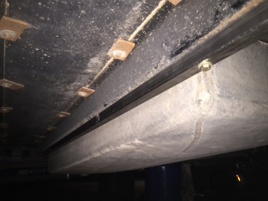
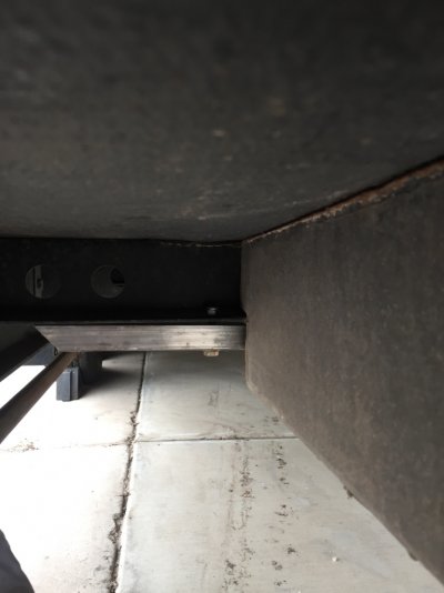
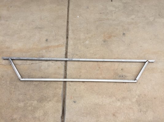
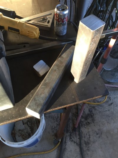
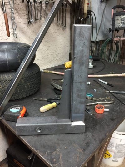
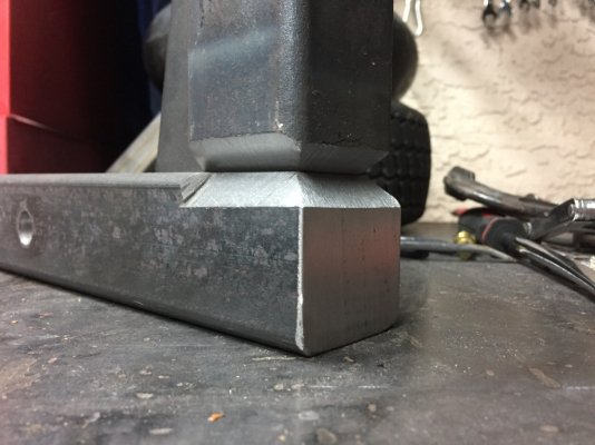
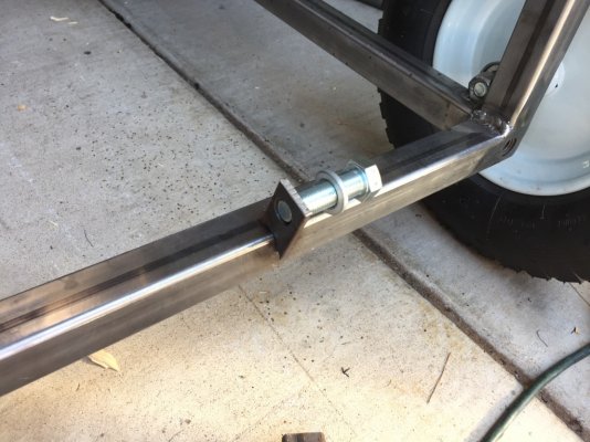
getting the angles to mate was kinda of a PITA but it was also kind of fun, that is the fabricator's conundrum! pics might be a little misleading: the bars are perfectly parallel and the ends are of identical length and exact same angles
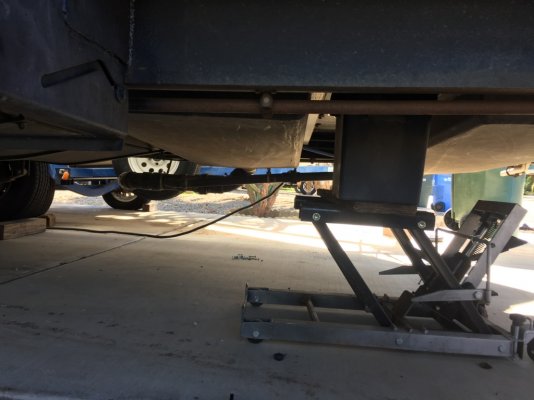
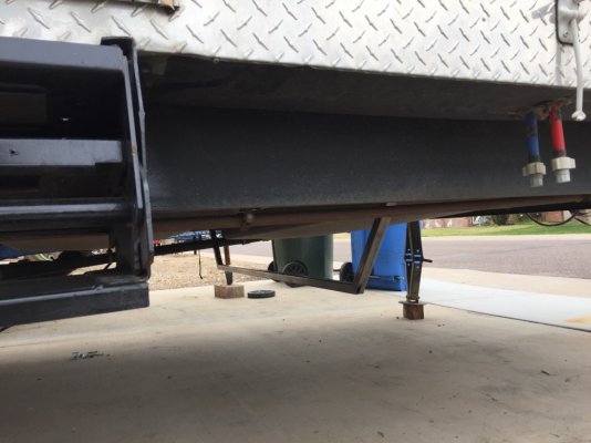
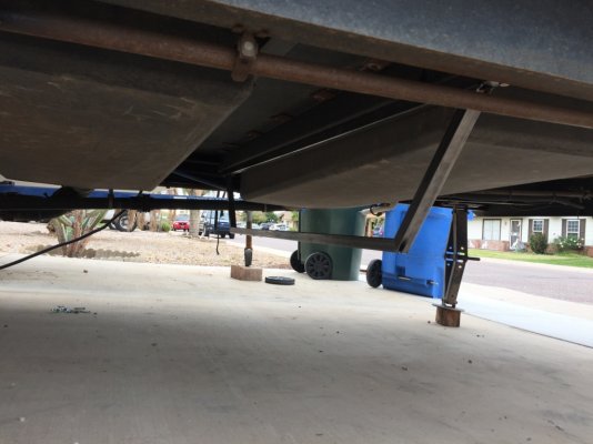
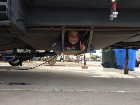
i'm SO on the fence with this project, this box will certainly hang low and i cant tell you if it's too low or not but i'm afraid it might be, the problem is my driveway slopes away from the house and the trailer is backed in, so the rear of the trailer is close to the ground while the tongue is several feet above so it sits level in these pictures and when it's level on level ground, this box will be closer to the ground
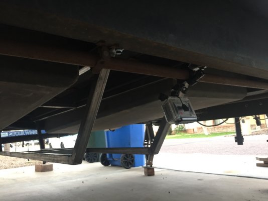
i'll continue making this cradle, at least tacking the rough frame together then hitch it up for a test drive, a big indicator will be simply having the tow vehicle wheels come off the sidewalk on to the street, if it bottoms out then, it's not good
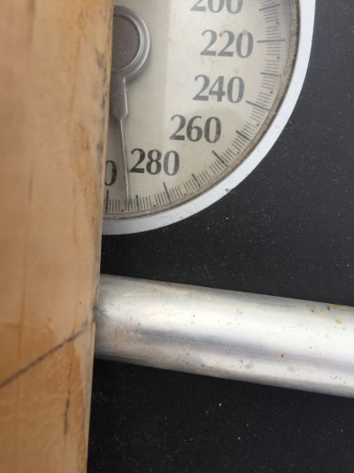
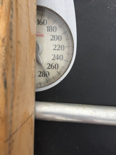
since i was concerned, i decided to re-weigh the tongue, with the 2 batteries on the tongue i'm at 1,172 lbs, with out at 1,100, i'd really like to be under 1,000 as a basis then adding weight before/after the axles to fine tune afterwards, at a minimum this tells me i can not add more batteries (weight) to the tongue
if the cradle doesn't work for clearance reasons, i'll consider some vented boxes in the rear most part of the only storage compartment although that will still require some tongue weight measurements, first world problems i guess
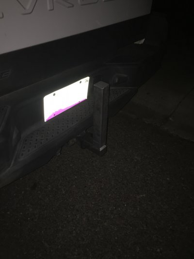
on a slightly related note i'm making a custom drop shank for my truck since the Harbor Freight shank in the weight distributing hitch barely (if at all) makes it level, I'd like to tip the scale a little and have it barely level on a too high note, so that extra height should help as well