OK, I spent the last couple of days installing the second half of the system.
I choose to go ahead with the install even if we get a new DP. I needed a project to do anyway and if I get a new one I will give this one to a family member.
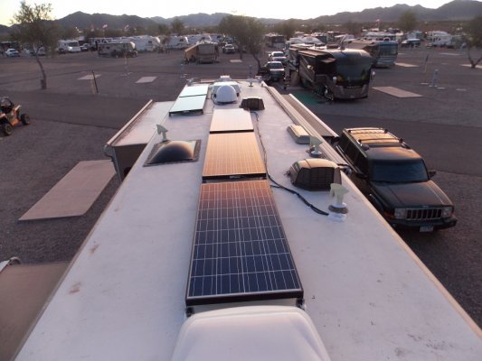
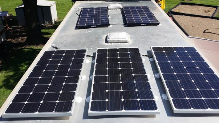
I upgraded my original plan for the DP from 290 watts, (two 145 watt panels), to 725 watts, (five 145 watt panels).
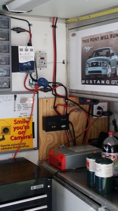
I also am doing something a little different. The Blue Sky controllers have a method of controlling more that one controller, ( Up to 8 controllers, a master and seven slave controllers) for expandability of the system. The Blue Sky 3000I is a 30 watt MPPT controller with a display and the ability to be the master controller with an IPN address of 0. I am using a Blue Sky 3024IL as the first slave controller. It is a 40 watt MPPT controller without a display and has the IPN address of 1. I probably will not add more capacity but I can add up to six more slave controllers.
These two systems are wired as two discreet systems and both put thier output into the same battery bank. They are networked and the master controller works to cooridinate charging the batteries. It also displays the combined total function of the networked system. One advantage of this configuration is that if one system has a problem, the other system will operate independently and the ability to expand the system if needed without rewiring or changing wire size.
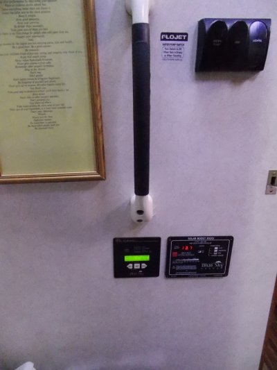
I also got an IPN Pro display that connects to the master controller, (3000I ) by way of a standard RJ-11 phone cord. This display uses a shunt at the negative post of the battery bank just like the Trimetric monitor.
I was going to use the Trimetric battery monitor based on recommendations by others on the Forum such as Kevin Means. The owner of Discount Solar here in Quartzsite assured me that the Blue Sky monitor has the same functions such as Amps in, Amps out, % of charge in batteries and such.
He also told me today that he is interested in how this system works in real life as this is the first actual configuration in this way that he knows of from Discount Solar.
OK enough of the description.
Here is the actual installation.
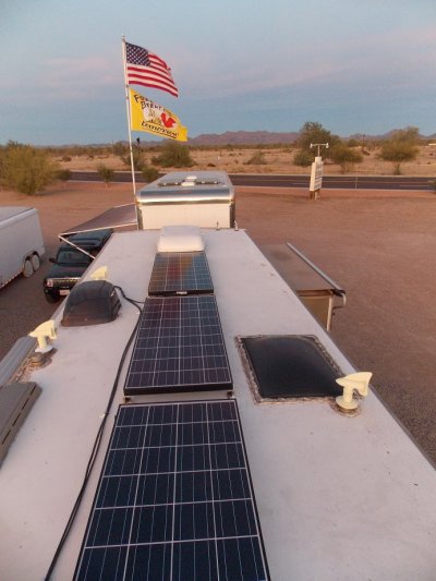
I mounted the panels so that there are no shadows on any of the panels. They can be tilted in either direction without causing shadows on other panels. I probably will not tilt them unless I am stationary for at least a month somewhere. However, if I did not install the tilt mounts I would not have this option.
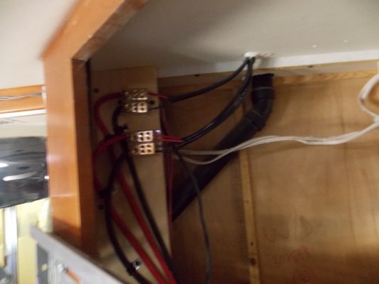
I wired them in parallel and connected the first two from the back to supply the 3000I controller. The next three I wired a little differently. The third and the fourth from the back are wired just like the first two and run thru the roof. The fifth panel from the back is the most distant from the roof entrance to the combiners so I was advised by the owner of Discount Solar to run it on its own seperate wire. The third and fourth panel input and the fifth panel input both connect to the same combiner block and then go down to the fuse and controller using #6 cable just like the first two panels do.
I drilled the hole thru the roof into a cabinet behind the TV in the bedroom. There is a wall space behind the cabinet that containes the vent pipe for the washer/dryer and that is what I used for bringing the wiring down to the controllers.
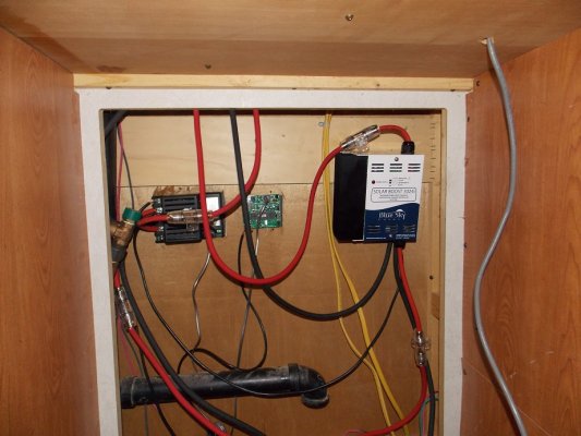
Now you will probably get a laugh out of where I mounted the Master controller and the IPN Pro Display. It is in the bathroom, clearly visable, and the buttons can be pushed from the throne.
The second controller, (3024IL) is mounted inside the wall and can be accessed from the cabinet where the washer/dryer used to be. I also used a little extra cable so that I could lift the controller off its hanger and work on it without being double jointed.
Both controllers have fuses on both the input from the panels and the output to the batteries. The 30 amp master has 40 amp fuses and the 40 amp controller has 50 amp fuses.
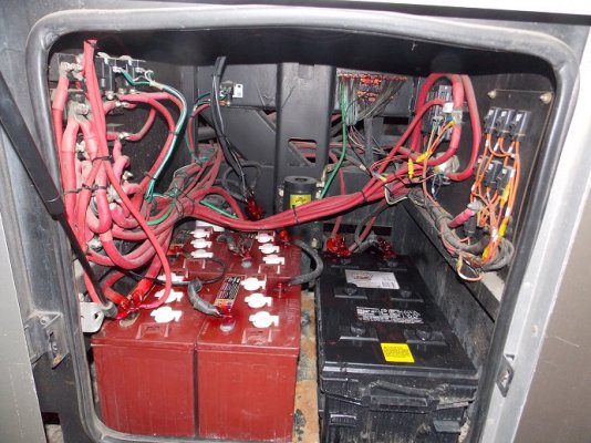
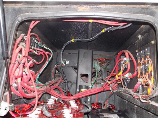
I was able to drill holes thru the floor directly into the battery compartment. Both positive output cables connect to the most positive post on the battery bank. In the following pictures it is the left nearest post. The two negative cables go to the shunt located at the right rear post where the twisted pair for the IPN Display also connects to the shunt. The temperature probe is connected to an available different post as it was tight on bolt length at the shunt post at the negative post. The temperature compensation wire goes to the master controller.
I used cable clamps to secure the cables to the ceiling of the battery compartment.
After rechecking all my wiring I placed the four fuses in the fuse holders and then went up on the roof and removed the cardboard that has been covering the panels since I installed them a few days ago. It was sunset as I removed the cardboard and took the pictures.
The displays show the status but tomorrow will tell the story about charge current.
Here are the pictures and I will probably post some in another post because of size restrictions.