Survey of Winnebago refrigerator replacements - gas to household

The friendliest place on the web for anyone with an RV or an interest in RVing!
If you have answers, please help by responding to the unanswered posts.
Well it is done! Before and a kind of after photo. Still have some trim on the bottom to do. Will have a complete write up in a couple days. Not a bad job, took longer than I estimated, but we only worked on it for about six hours a day for five days. Most of it was doing something, looking at it and then taking it out and changing it. Doing something, thinking about it overnight and changing it in the morning. Learned a few things and hope to share with others going down this path. All in all, I think it was a great change.
 

Attachments

  • Old Norcold.JPG
    Old Norcold.JPG
    313.1 KB · Views: 33
  • New Samsung.JPG
    New Samsung.JPG
    287.6 KB · Views: 40
Good show old boy! You lost your drawer but what a great trade-off! You certainly spent the time to do it right the first go-round. I had my incredibly talented buddy Bob help me when we did our transplant, two heads (especially his) made the job go much quicker and without any issues.

Looking forward to more pix.
 
Though not 100% complete - here goes - Will include a link to a blog post that integrates the photos better at a later date. This will be long, so I will break it up and attach photos to each post to keep them with the text. Also, as with other projects, I intended to take photos at each step, well once we got started, the camera kind of got forgotten. I am also copying from the original document, so we will see how the formatting holds up.

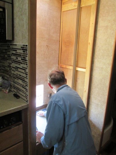
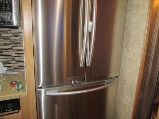
Started refrigerator replacement project at about 11AM. Used the steps listed in my outline and ran into very little problem.

  • Turn off refrigerator
    Turn off Propane at tank
    Clean out refrigerator and freezer
    Turn off refrigerator electrical breaker
    Removed exterior access panel ? from there -
    Unplug the 120v supply
    Disconnect the 12v power Supply
    Disconnect Propane Line
    Cap Propane line with Watts Compression fitting cap ? Use Pipe Dope- Not Teflon tape(we      capped at main feed line)
    Disconnect and cap water line ? leave valve in place at this time
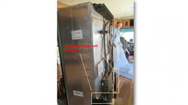
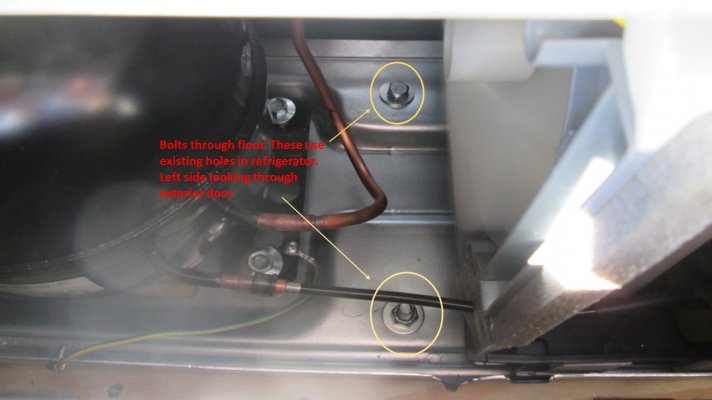
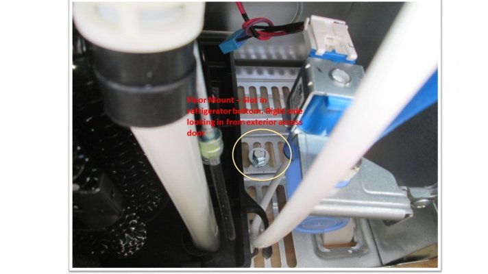
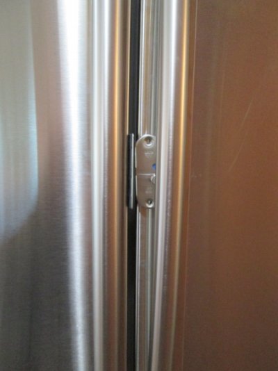
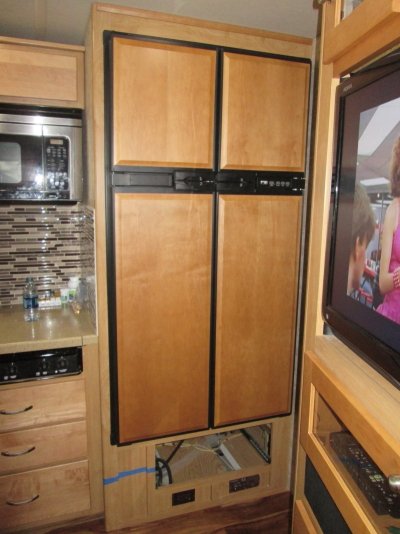
    Remove any obvious mounting/securing screws (found two on each side. Bolts that go into captive nuts on Motorhome mounted flange.)
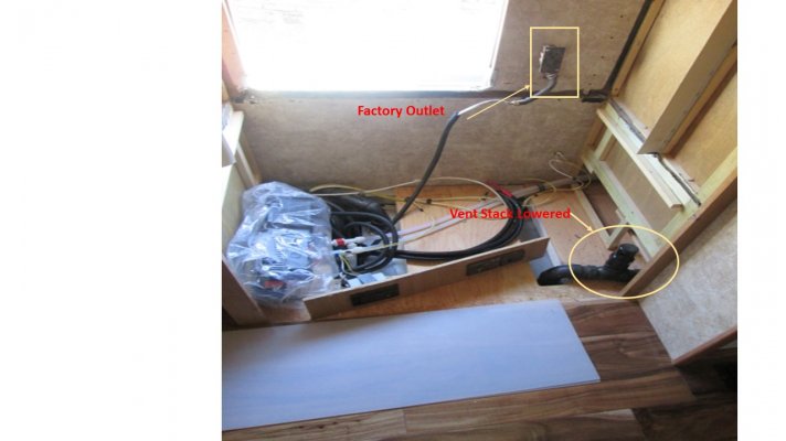
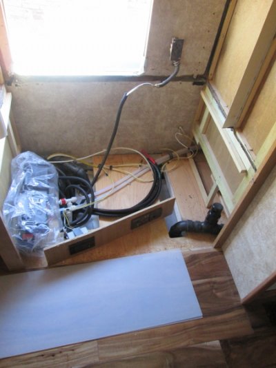
    Remove Refrigerator Vent Cover ? from roof ? (My vent cover was destroyed in a wind incident enroute to the location we were doing the swap. Held on by bungee cord and duct tape)
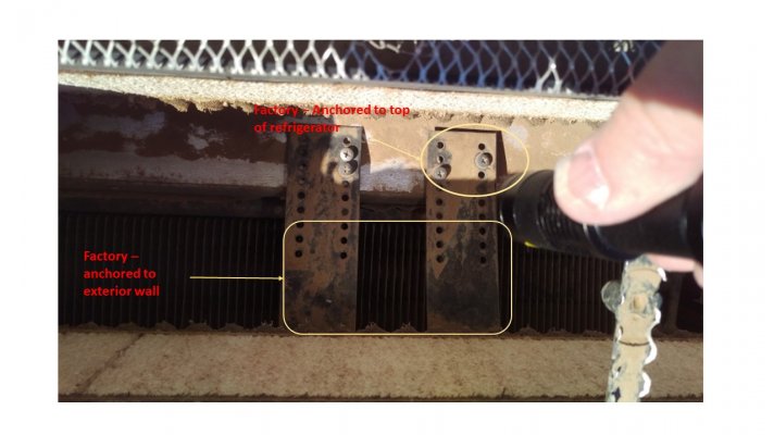
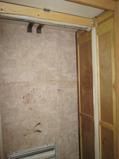
    Through vent, see if any securing screws are evident ? (found two straps mounted to exterior Motorhome wall and four screws into top of refrigerator)
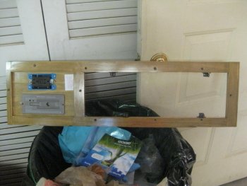
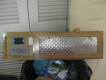
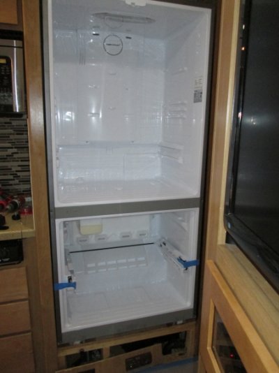
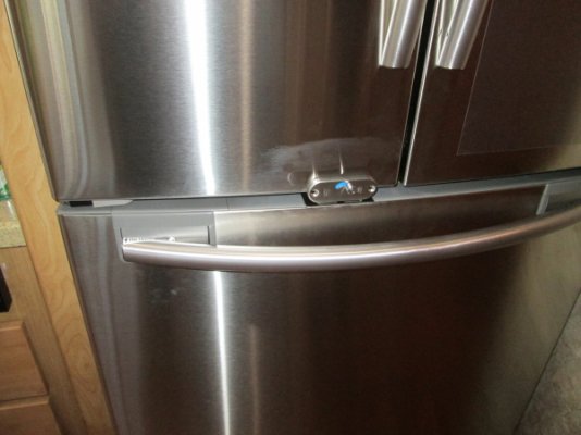
    Remove all refrigerator doors
    Remove shelves, drawers and other loose parts inside refrigerator & freezer.
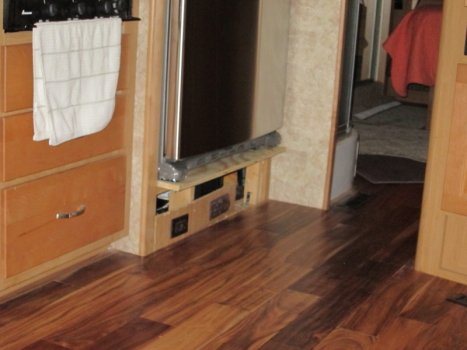
    Remove drawer below the refrigerator
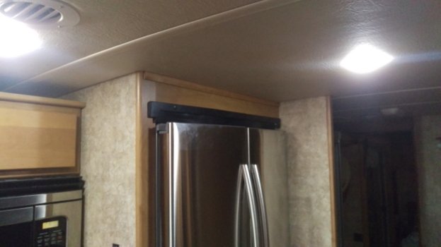
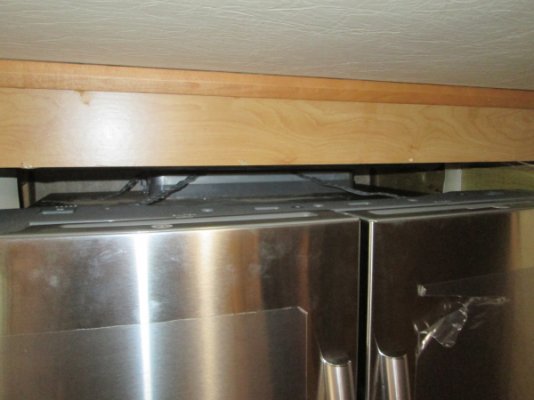
    Remove any trim pieces around and across top of refrigerator (top and bottom trim is screwed through a flange surrounding the refrigerator into the wood cabinetry that surrounds the refrigerator. Screws were covered with caps. Side trim just ?snapped? into the flange along the sides of the refrigerator)
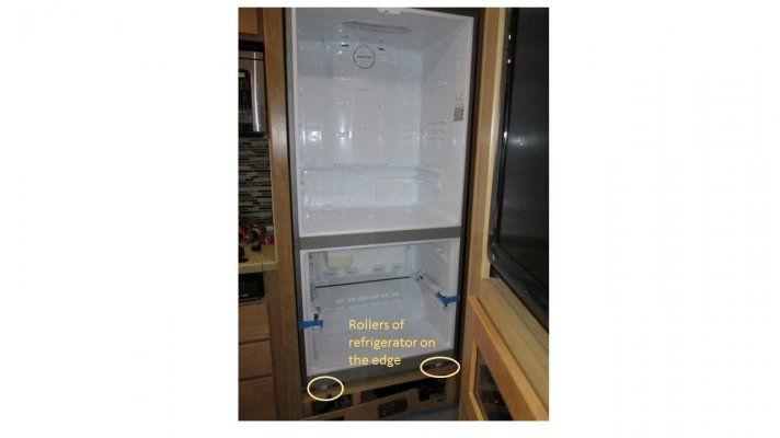
    Attempt to slide refrigerator out of opening -
    If it moves ? create platform with dolly to slide refrigerator onto -
    If it does not move, look for other screws or bolts holding it in place and polyurethane adhesive
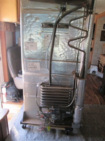
    Slide refrigerator onto dolly and move to center of living area
    Remove cooling unit from back of refrigerator ? Make lighter ? if necessary(we did not do this)
    Carefully tip refrigerator on narrow side, slide down 2x4 ramp on entrance stairs and out of MH (see narrative for how we removed the refrigerator from the Motorhome)
    Reassemble refrigerator, install doors, cooling unit ? if removed.(We left it in pieces)                                           
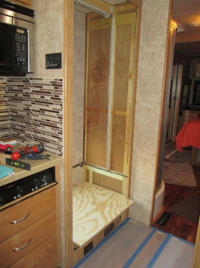
    Remove existing Refrigerator floor
    Remove drawer hardware
                                 

The refrigerator was held in by two straps on top going from the side wall to the top of the refrigerator, and held to the top with four not very efficient screws.
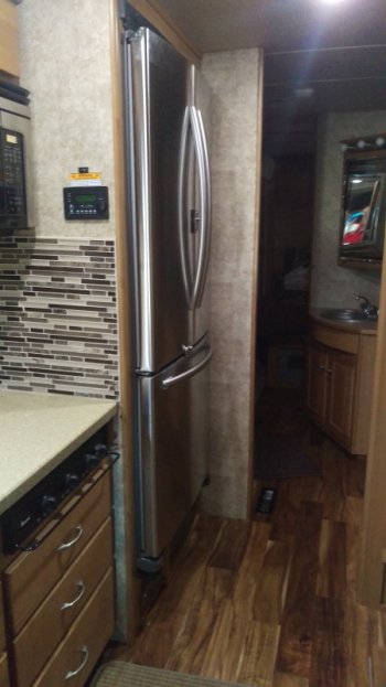
Found the four bolts, two in each side that went through metal plates attached to the side of the refrigerator and into metal plates mounted to the interior wall of the motorhome. These bolts were easy to get to. The interior edge of the refrigerator has a flange around it that has screws into the wood cabinetry at both the top and bottom of the refrigerator. These screws are cover with caps. Gas line disconnected and later removed entirely. Pushing from the back freed the refrigerator and let it slide forward. We did find polyurethane sealant/adhesive on the bottom of the refrigerator. Dan and I then slid it completely out and lowered onto the furniture dolly. We then moved it into the center of the motorhome where we then removed the steel flanges along both sides in the back. These flanges bolted to the wall plates in the back.
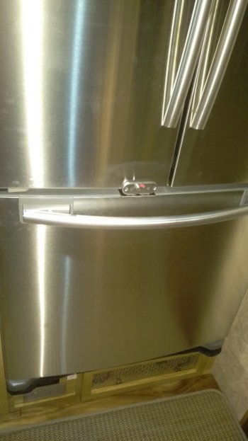
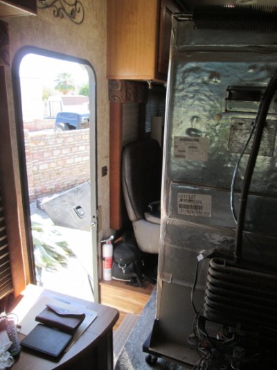
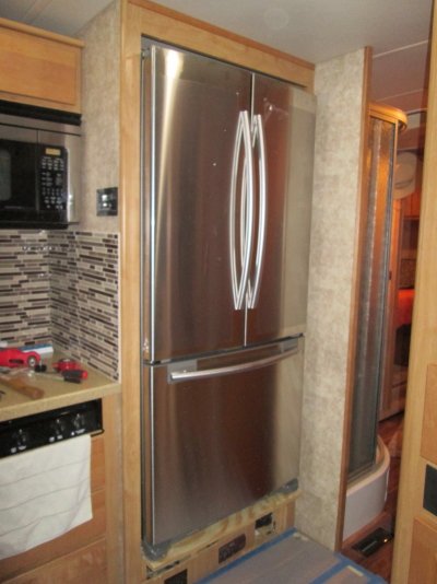
We then positioned the refrigerator in the doorway, removed it from the dolly and laid it on its side. The dolly was then placed under the refrigerator side toward the top. We put the heavy end out the door first. With one person outside on the heavy end and one person on the "light" end controlling the dolly, we were able to "roll" the refrigerator out the door and gracefully down the steps. Since this is a side entry motorhome, the doorway is 27 inches wide. We did remove the grab bar on the back side of the door and this gave us the full width. The refrigerator with the cooling unit measures 25 inches wide at the widest point which is where the stack is. Once out of the motorhome Dan and I could easily carry the refrigerator to a spot outside his fence along the street. All on the doors that we had removed were stacked there also, and about five hours later some people showed up and asked if they could have it. Off it went in the back of a trailer.
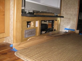
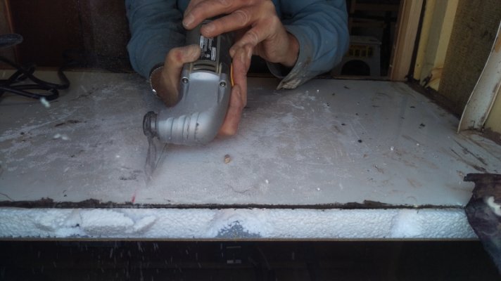
With the refrigerator out we needed to remove the existing floor and framing. The existing floor was held in place with polyurethane sealant and two screws. The drain pan for the refrigerator was plastic mounted along the back wall about four to six inched wide. We removed the drain pan first, cutting it with a multi tool into sections.
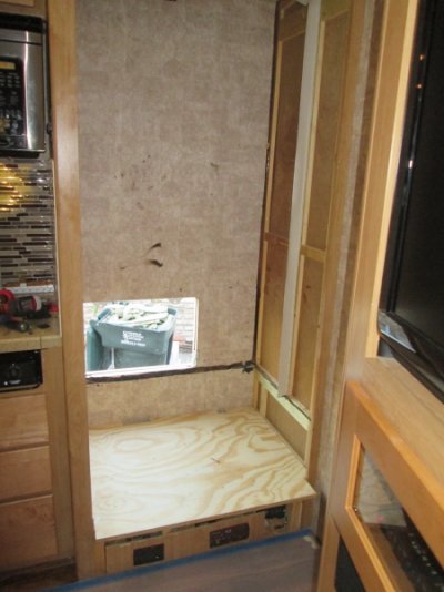
Once that was removed we simple cut the floor from front to back with the multi tool and removed it in two sections. The floor appeared to be a piece of motorhome side wall that was left when a window opening was cut into a side wall during the construction. It consisted of a piece of Luan, two inches of white open cell foam and then the exterior filon or fiberglass.
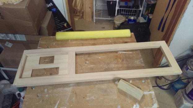
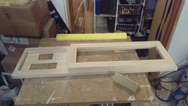
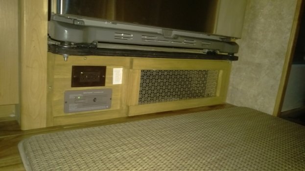
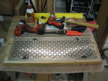
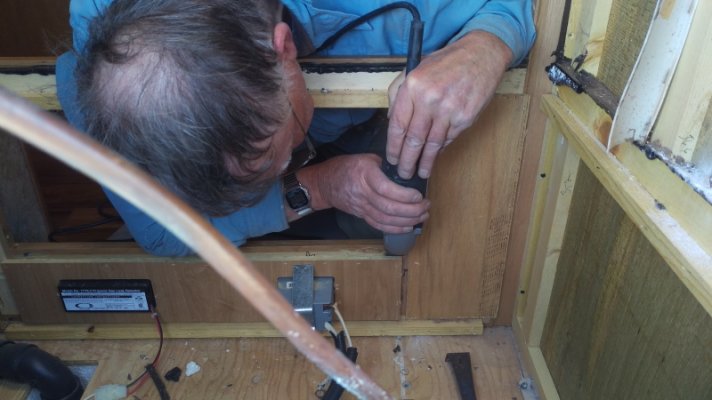
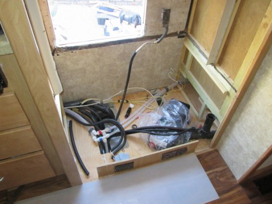
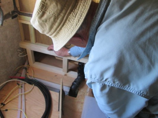
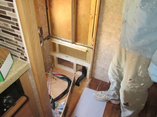
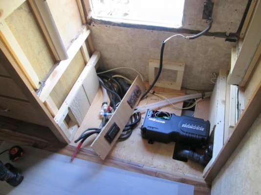
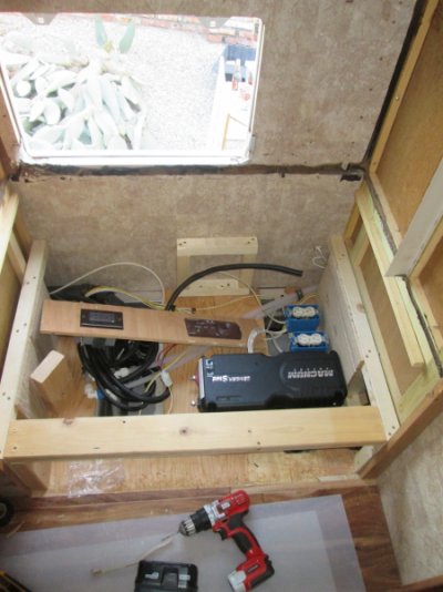
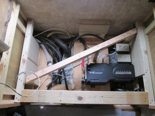
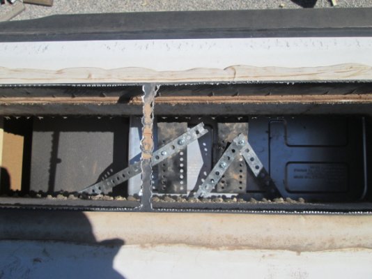
Having removed the floor, we found that the frame work that supported it was 3/4 x 3/4 wood strips, with a occasional 3/4 x 2 inch piece serving as a vertical support. There was no center support structure. This kind of gives testament to the strength of the laminated side wall, at least this small section. We removed the frame work along the edges and some light metal angle material that was screwed horizontally along the back wall. We then started the removal of the cabinet framing on the inside of the motorhome. we did this with great care as the original plan was to shorten it and reuse it. This frame work contained the opening for the drawer, and below that the mounting area for both an electrical outlet and the gas detector. These two items were mounted in particle board that was stapled to a 3/4 thick frame. the material used to create the frame was a particle type board covered with wood grain vinyl. This was slow going as we cut through staples and carefully pried things apart so as to not create more damage. This was very slow and in hind sight probably not worth the effort. The frame of rails and stiles (cabinet talk) were held to the refrigerator side framing with some 3/4 x3/4 strips staple to the inside frame, which was then screwed to the interior supports. The project continued after a beer and sandwich. Since we needed to put an inverter under the refrigerator, we needed to run two 1/0 and one #6 cable from the refrigerator to the batteries. The easiest path was to removed the drain line and use that hole for one cable (inside split loom) and the hole that the gas line went through was used for one 1/0 and the #6 cable, both inside split loom. Since the propane tank sits directly below the refrigerator it made finding and running the wires much easier. One more hole had to be made to accommodate the battery sensor wire for the Inverter. This did not take much as the exterior floor is just two layers of thin metal with foam insulation in between. This sensor cable was also placed in split loom. With that part started (wire in the split loom and run through the floor and stretched out along the ground we could move to other tasks. We found that the gray water tank sits in this area, below the refrigerator, and the area that the wiring and gas lines penetrate the exterior floor is beside the tank. Care was needed to make sure that any holes that had anything put in from the top did not penetrate the tank. The sub-floor is ? plywood with 2 inch white open cell foam (foam is easily pulled apart) with another layer of plywood underneath. Dan  started on the design for the new floor. We decided to use 2x2 material. This was easy to source (big box store) and to work with. It was off to the store for supplies and the end of day one.


Attachments

  • Top Mount - Notation.jpg
    Top Mount - Notation.jpg
    140 KB · Views: 26
  • Top mounting bracket.JPG
    Top mounting bracket.JPG
    242.9 KB · Views: 20
  • Back side of Norcold.JPG
    Back side of Norcold.JPG
    299.7 KB · Views: 20
  • Mounting Flanges - Notation.jpg
    Mounting Flanges - Notation.jpg
    96 KB · Views: 18
  • Ready to leave the building.JPG
    Ready to leave the building.JPG
    271.5 KB · Views: 25
  • Dan examines original floor.JPG
    Dan examines original floor.JPG
    255.3 KB · Views: 22
  • Cutting original refrigerator floor.JPG
    Cutting original refrigerator floor.JPG
    280.3 KB · Views: 22
  • Removing mounting board for outlet_detector.JPG
    Removing mounting board for outlet_detector.JPG
    317.8 KB · Views: 21
Continuation - You might also check posts #10, 14, 16, 33 and 41 for a little history and some "before" pictures.
Day two found us starting out with the layout of the frame for the refrigerator floor. First thing we needed to do was lower the vent stack of the grey water tank. We purchased a female threaded collar and cut the existing vent stack off to about an inch above the fitting into the tee. We glued the collar on above the Tee and then threaded the vent fitting onto the Tee. This lowered the stack about three inches. Since the vent cap has a one-way valve it in, hopefully we will not get any water (or fumes) splashing out as we drive down the road. We had looked at alternate routing locations, but could not find one that would work. Since we decide to use 2x2 material, which is easy to handle, a small 4.5 inch circular saw was used, (Compound Miter saw would have been better) to cut a series of 6 1/4 inch uprights. We then measured for our front to back stringers. We glued the uprights and put them between a top and bottom stringer, screwing them through both top and bottom stringers. We then took some 1/2 inch plywood and made a gusset that we then attached to the upright and the top and bottom stringers, with 1 ? 18ga brads, like making a truss. We then anchored the bottom stringer to the subfloor with glue and screws. The end frames we also anchored to the sidewalls. We built a small center frame that we attached to the outside wall of the motorhome. We then located the UPS unit where we wanted it and anchored with some 3/4 x 1 lag screws. Then a diagonal frame was built that goes from the rear right corner to the left front corner. This gave us the center support. A front stringer was made with a 2 x 4 flat and using three 2 x 4 uprights. This gave us the front support, a little stronger than the 2 x 2 stringers. We positioned the uprights in a fashion to give an opening about 9 1/4 x 16 for access to the outlets and the inverter. The battery cabling was run for the inverter. We were fortunate that we were able to follow an existing wiring bundle back to the battery cabinet. Not that this was without a little difficulty, but much easier than we had envisioned when we first looked at the problem. To get past the axle, I ran a fiberglass wire fish rod along the existing wire bundle, connected the cable and pulled it through. For the refrigerator floor, a piece of 3/4 plywood was sourced and a trial fit was made. The initial cut was made with the width of the opening, about 34 inches x 25 inches deep. This put the front edge of the floor right at the edge of the cabinetry. That ended the second day of construction.
 

Attachments

  • Working on the vent stack.JPG
    Working on the vent stack.JPG
    274.2 KB · Views: 22
  • Vent Stack - Outlet - Notation.jpg
    Vent Stack - Outlet - Notation.jpg
    117.2 KB · Views: 18
  • Vent stack lowered.JPG
    Vent stack lowered.JPG
    246.2 KB · Views: 19
  • Test fitting side frame.JPG
    Test fitting side frame.JPG
    265.8 KB · Views: 17
  • Side frame in place.JPG
    Side frame in place.JPG
    272.6 KB · Views: 19
  • Side_Back frames in place.JPG
    Side_Back frames in place.JPG
    278.9 KB · Views: 19
  • Front Frame.JPG
    Front Frame.JPG
    268.1 KB · Views: 23
  • Frame and Inverter in place.JPG
    Frame and Inverter in place.JPG
    279 KB · Views: 21
Continuation -
On day three we decided to add a gusset to the frame against the outside wall. Again we used a piece of 1/2 inch plywood. Metal angle braces, metal "T" braces and metal corner braces were added in various locations on the frame work to give the frame more structural rigidity. Connections were made to the Inverter using end connectors that are held to the wire with set screws. These connectors were then well taped with the proper color tape to show polarity. We used 1/0 for both the positive and negative lines and #6 for the frame ground. All three were flexible welding cable which made working with it much easier. Connections at the battery were made using the same type of connector. The positive cable goes through a 200 Amp T Class fuse in a holder that includes a clear plastic cover. The cable is held to the fuse with set screws. A ground wire connector, normally seen in a home circuit breaker panel was used to make the frame ground connection. The remote for the Inverter was mounted in the wall to the right of the microwave. Not a great location as you cannot get directly in front of it, but a usable location. Once the hole was cut, since we had access to the back side, two furring strips were added for the mount screws to penetrate. The remote cable was shortened to the proper length so that 30 feet of wire did not have to be stuffed between the wall and the refrigerator. With the Inverter in place and connected to power, it was load tested with a small vacuum cleaner and it worked perfectly. The floor was then trimmed and notched in the back to accept the refrigerator power plug. With these things done, it was wait for the refrigerator which is scheduled for Tuesday.

Day four was a day of frustration. The Home Depot crew (actually GE) delivered the refrigerator at about 10:45. As soon as they saw it was going into a Motorhome, they stated no way. They stated that it was considered a liability issue. If they delivered it into the Motorhome and the refrigerator fell over damaging property or people that they could be sued. An offer of $20 ea did not work. So after unboxing the refrigerator and confirming no exterior damage - off they went leaving the refrigerator sitting next to the Motorhome. The next 45 minutes was spent taking the doors off the refrigerator, removing the freezer drawer/door and other items, like the trim over the levelling feet on the front and the bracket to hold the levelling foot. Then Dan and I and a couple of his friends hoisted the refrigerator into the Motorhome. This refrigerator is a little heavier than the Norcold, but not by much. Once inside we put it on a furniture dolly and moved it into position in front of the opening. We did not build up the level of the furniture dolly to the same as the refrigerator opening, and that would have helped. So, we lifted it into the opening and pushed it back into place, tight against the back wall and the next frustration happened. Though the refrigerator is only 24 inches deep, for it to sit properly on the floor, the floor needs to be deeper than 25 inches, which is what we built. The wheels on the refrigerator were on the edge of the floor, I mean inhale deeply and the wheels would roll off the edge of the floor causing the refrigerator to tilt forward. So, the question got to be what can we do to resolve the problem. The ideas ranged from adding another 1.5 inches on front of the floor and opening with a 2x4, to building a bracket to hold the refrigerator in place anchored to our existing frame, removing the wheels somehow and hope that the bottom of the refrigerator would support the weight, but still leave ventilation, to cutting a new piece of floor that would extend past the front of the refrigerator enough for the leveling feet to sit on it. Anchoring the refrigerator was also part of the discussion. Long story short, we removed the refrigerator and cut another piece of 3/4 inch plywood. This time we cut it at 29 inches deep, about four inches deeper than the first one. This gave us ample room to place the refrigerator, and set it a couple inches away from the exterior wall. Once we had the new floor piece cut and set in place, we positioned the refrigerator on the new floor, and marked where the front levelling feet would set, except we had removed the foot and would drill a hole in the floor to accept a bolt. We also marked three locations through the exterior refrigerator door where we could place bolts to anchor the refrigerator to the floor. These locations through the base of the refrigerator were near the center and left side (looking at the refrigerator from the front) of the refrigerator. There was no way to reach to the right side (again looking at from the front) to mark any holes. The holes through the plywood where the levelling feet reside was reinforced with an 18-inch piece of predrill steel 1/16 thick strap. This was anchored at four points with 3/8 by 1 1/2 inch lag screws. The intent was to reinforce the hole in the plywood should the refrigerator try and slide forward into the Motorhome. The refrigerator was put back into place and it was anchored through the floor both front and back using the holes that we had drilled. Through the holes we used 5/16 diameter bolts with fender washers and nylock nuts. We found that since the power cord came from the top of the refrigerator we were short about 2 inches of reaching the outlet under the floor. This was solved with a short extension cord. The shelves were replaced into the refrigerator, it is a good thing to do this prior to replacing the doors, as the doors might not open enough to get the shelves in. The doors were installed, though there is little clearance once the refrigerator is installed, it is doable. The freezer drawer was assembled, the baskets lift out and the door comes off the rails. The unit was plugged in and seems to function properly.
 

Attachments

  • Frame and Inverter in place.JPG
    Frame and Inverter in place.JPG
    279 KB · Views: 20
  • New Inverter Control.JPG
    New Inverter Control.JPG
    253.2 KB · Views: 21
  • New Refer in place - Problems.JPG
    New Refer in place - Problems.JPG
    218.1 KB · Views: 28
  • Rollers - Notation.jpg
    Rollers - Notation.jpg
    78.2 KB · Views: 20
  • New floor - 4 inches bigger.JPG
    New floor - 4 inches bigger.JPG
    271.7 KB · Views: 23
  • New Floor.JPG
    New Floor.JPG
    251.4 KB · Views: 23
  • Floor Mount Locations - Notated.jpg
    Floor Mount Locations - Notated.jpg
    121.7 KB · Views: 22
  • Floor Mount Right side.jpg
    Floor Mount Right side.jpg
    115.7 KB · Views: 22
  • New Refrigerator Installed.JPG
    New Refrigerator Installed.JPG
    287.5 KB · Views: 28
We converted by hanging to a newer unit.  Does this count?  It was #1 on DW wish list just ahead of stack W/D.
 
Continuation -
Day five we woke to a nice cold refrigerator (38 degrees) and a chilly freezer (-2 degrees). Today we reviewed our anchoring system and decided to add two blocks, one on each side of the exterior access door, to keep the refrigerator from sliding backwards. We also installed three straps to the top of the refrigerator. Coming from the factory installed anchor point, one strap was placed to both front corners and anchored to the top of the refrigerator using the screws that hold the top control panel in place. A third strap connects from the factory anchor to the top of the refrigerator in the rear (left) side, toward the inside of the Motorhome. Two self tapping #8 by 3/4 were used.
Spacers will be added under the leveling foot bracket - right now it is just a 5/16th bolt going through the foot and through the plywood, with a fender washer and nylock nut on the bottom. Nothing really for the bracket to sit on.  Door latches were also added to the refrigerator. Don?t want the doors flying open as you drive down the road. We used ?Lamp Locks,? these are the same used by several RV Manufacturers. We placed one in the center of the door handles to hold the two doors together. Another was placed on the left door connected to the freezer drawer. We contemplated putting it on the side of the freezer door to the frame, but I was concerned with it getting in the way of the drawer to frame seal. I used 3M mounting tape ? the 85 pound variety. The doors stayed closed on our 800+ mile trip home.
The final step in this process will be to finish out the opening below the refrigerator. Across the top and down the sides. - This has to wait as the Motorhome is currently in the shop getting the patio awning replaced, paint repaired and other items from a high wind event on the trip to Yuma.
 

Attachments

  • Anchor straps attached to factory anchor.JPG
    Anchor straps attached to factory anchor.JPG
    263.8 KB · Views: 21
  • Anchor straps on top of refer.JPG
    Anchor straps on top of refer.JPG
    230.8 KB · Views: 21
  • Travel Locks Installed.JPG
    Travel Locks Installed.JPG
    255.1 KB · Views: 18
  • Door Travel Lock - 3M Mounting Tape.JPG
    Door Travel Lock - 3M Mounting Tape.JPG
    213.2 KB · Views: 19
  • Freezer Travel Lock - 3M Mounting Tape.JPG
    Freezer Travel Lock - 3M Mounting Tape.JPG
    220.4 KB · Views: 22
  • The Old_sm.JPG
    The Old_sm.JPG
    210.2 KB · Views: 22
  • The New_sm.JPG
    The New_sm.JPG
    196.1 KB · Views: 24
mickey53usa said:
...The Home Depot crew (actually GE) delivered the refrigerator at about 10:45. As soon as they saw it was going into a Motorhome, they stated no way. They stated that it was considered a liability issue. If they delivered it into the Motorhome and the refrigerator fell over damaging property or people that they could be sued. An offer of $20 ea did not work....
Sorry my $20 tip idea didn't work, we were in a rural area and the Lowe's delivery guys had zero hesitation to take the twenty bucks and carry our new fridge in the coach. (I have news for those delivery guys, they could be sued for any reason no matter how frivolous.)

So, we lifted it into the opening and pushed it back into place, tight against the back wall and the next frustration happened. Though the refrigerator is only 24 inches deep, for it to sit properly on the floor, the floor needs to be deeper than 25 inches, which is what we built. The wheels on the refrigerator were on the edge of the floor, I mean inhale deeply and the wheels would roll off the edge of the floor causing the refrigerator to tilt forward. So, the question got to be what can we do to resolve the problem....
Adding to the platform to accommodate the front wheels was the right tactic. Winnebago removes the wheels (or they have a special arrangement with the fridge manufacturer to not install them) which would make service much more difficult if the fridge needs to be removed.

Very well done job and thanks for such good documentation. The fun part of a DIY job like that is you have an intimate understanding of the fridge installation and what plumbing and wiring is in the area.

You might find you have to run a drain outside from the pan (or from the tube that goes to the pan) but it might evaporate fast enough to where it won't slosh out when underway.

A general carpentry note: I like to use poplar wood instead of soft pine for a project like this. Poplar is a more dense wood (but not as dense as a hardwood) and resists splitting when using fasteners (and is stronger.)

A general primary wiring note: I've been under the impression that welding cable was not the best choice for 12V heavy current applications in an RV but after doing a little research, I think it is entirely suitable and a better choice than battery cable. When we owned sailboats, I always used tinned cable due to the propensity for bare copper to grow the green 'fuzzies.'


schoolsout2 said:
We converted by hanging to a newer unit.  Does this count?  It was #1 on DW wish list just ahead of stack W/D.
Hanging to a newer unit? Not sure what that means. Anyway no pictures means it doesn't count  :D.)
 
John, we could find no evidence of a drain pan or drain tube when we examined the refrigerator before installing it. Going through the manual there is no mention of an evaporation pan or drain line.

Regarding the welding cable - I did a lot of research regarding welding versus battery cable. Deciding point was when I looked in my battery cabinet and all the cabling is welding cable. Felt if it was good enough for Freightliner or Winnebago, it was good enough for me.

One think I did find was no way to turn off the refrigerator. I planned to do that by turning off the circuit breaker that the "old" refrigerator (now the new UPS) was on, then I discovered that same circuit also have the Converter Charger on it. So, plan "B" is to add a switch to the Inverter output. Then I just turn off the "outlet" that the refrigerator is plugged into.
 
mickey53usa said:
.....One think I did find was no way to turn off the refrigerator....
We couldn't figure out how to turn off our Samsung fridge in the stick house so we unplug it when we leave. Fortunately our Horizon was already wired for the fridge outlet to be on the inverter so we flip that breaker when we move off the coach.
 
To complete this saga, we will start with a few things we found on the trip home from Arizona where we installed the refrigerator.
First thing we found was that the shelves in the refrigerator were not in the proper location. An easy fix, until you realize that the shelves can easily be adjusted if you can get the refrigerator doors open to a complete 180-degree angle. Well, guess what, the left door will come close, but there is no way the right door will open that wide. So, off with the right door so you can get the shelf in the proper place.
The next thing we found was that this make/model of refrigerator does not have an on/off switch. Once you plug it in it is on. I thought that the outlet that I was using for the A/C power to the refrigerator (Inverter 120v inbound) was a dedicated circuit. It is a dedicated circuit, but it has both the refrigerator and the Converter/Charger on it. So, I could turn off the circuit and shut off the refrigerator, but would lose the charging of the batteries when the unit was plugged into 120v power in storage. I could have used the charger in the Inverter to charge the batteries but it seemed like it would be more hassle than it was worth. It would also cause a situation where if the A/C power went out, when it was restored the Inverter would come on and the refrigerator would come on. So, I opted to put a switch on the A/C out of the Inverter. Now, I just turn the switch on above the Inverter control panel when I want the refrigerator and turn the switch off when we park the Motor Home in storage. These items were very minor and both could have been avoided with a little more pre-planning.

The next part was to do something with the space under the refrigerator and to the platform that extends out underneath it.
Filling the space underneath was relatively easy. I already had a design in mind on how to accomplish this. It did change a little, but not a lot. I knew that I needed to have access to the Inverter, so that meant a door of some sort. I knew that I had the propane detector and an electrical outlet to mount. I envisioned a frame that had a panel on one side for the electrical outlet and the propane detector and the other larger side would have a door that could either be opened or removed to service the UPS.
I envisioned using the solid maple drawer front that I had removed as the door. I could try and stain wood frame as closely as possible to the existing frame work. I started by building the frame. I had taken measurements and drawn a diagram, but the work got slowed because I did not have access to the motor home to test fit the frame, as it was in the shop awaiting parts and repairs. The motor home had been damaged by a wind event on our way to Arizona. This incident has been posted in on-line RV forums and discussed and dissected to death. For the frame, I used 11/2x3/4 Ash wood imported from New Zealand (available at Home Depot). I used a piece of ? plywood for the panel to hold the electrical outlet and the propane detector. (Propane Detector was replaced as the original one is about eight years old.) This left a decent sized opening in which to get to the main items on the Inverter if necessary. Then I started on the door to cover the opening and things ground to a halt. I could not in good conscious cut that 20x14 piece of solid maple down to 7x18. It is much to nice to do that.
So, I built another frame from wood, slightly smaller than my opening. Some stamped aluminum vent material was obtained to go on the back of the just competed frame. When in place it looks like the cover over the HVAC filter/return air, just smaller. It will also provide more ventilation for the Inverter. This cover is held in place with latches that have a diamond shaped protrusion on one piece and a unit with double rollers on the other stationary side. The post goes on the back side of the cover and the double roller mount on the edges of the opening. When you put the cover on the posts go into the double roller. The main frame is anchored with screws into the refrigerator floor framing. Only two screws are visible and those are covered with wooden ?buttons? that are stained the same color as the rest of the wood.

The next part was the floor that the refrigerator sits on, specifically the part that comes out past the wall cabinetry.
Since we were not able to turn the leveler feet brackets inward and still use them as an attachment point for anchoring, they protrude out from the refrigerator a little. With the factory cover on, they stick out just slightly passed the closed doors of the refrigerator. One of the things that I did was to cut some circular pieces of wood the same diameter as the leveling feet for spacers. I then ran the anchor bolt through the floor, through the spacer then trough the leveler bracket and put a nylock nut on. When I tighten this bolt, it gives the refrigerator something to ?sit? on other than air.  For safety sake, the bolt goes down from the top with the nut on the bottom, so if the nut comes off at least the bolt is still in place to provide a little level of security in keeping the refrigerator from moving. I then traced around the bottom of the refrigerator in the front and using a combination of a scroll (saber) saw and a vibrating multi-tool, cut that shape into the plywood floor. After some sanding, I painted all the expose plywood of the refrigerator floor black. Once the factory cover is in place, the floor is not that noticeable.

Next came closing the two (2) inch gap at the top of the refrigerator. I had kept the black trim that was around the Norcold and tried to envision a way to use it in conjunction with something else to cover or close the gap. I ended up using garage door seal that is intended to go on the bottom of the garage door. It is about 3 inches wide and has a rib on the top and bottom that is about ? inch wide. I cut the rib off one side, and then used the trim piece from the original refrigerator to hold it in place. I may try and use a vertical strip also from the original refrigerator to go down along the refrigerator. It was attached to a flange on the refrigerator and probably will need to be glued in place.
 

Attachments

  • Starting point - finishing installation_sm.JPG
    Starting point - finishing installation_sm.JPG
    151.1 KB · Views: 16
  • Main frame during assembly_sm.JPG
    Main frame during assembly_sm.JPG
    187.6 KB · Views: 15
  • Main frame with the cover frame on top_sm.JPG
    Main frame with the cover frame on top_sm.JPG
    185.9 KB · Views: 16
  • Completed project below refrigerator_sm.JPG
    Completed project below refrigerator_sm.JPG
    168.1 KB · Views: 17
  • Closing the top gap_sm.JPG
    Closing the top gap_sm.JPG
    154.2 KB · Views: 18
  • Completed project_sm.JPG
    Completed project_sm.JPG
    154.7 KB · Views: 18
  • Side view of completion. Switch above the Inverter Control_sm.JPG
    Side view of completion. Switch above the Inverter Control_sm.JPG
    181.1 KB · Views: 22
Thanks John -

Here are a couple more photos of the bottom "frame."
This is the first project that I used Pocket Screws on - Think I am hooked on them now -
 

Attachments

  • Back side of the cover._sm.JPG
    Back side of the cover._sm.JPG
    126.6 KB · Views: 18
  • Frame without the cover_sm.JPG
    Frame without the cover_sm.JPG
    98.4 KB · Views: 15
  • Complete frame-cover before install_sm.JPG
    Complete frame-cover before install_sm.JPG
    100.1 KB · Views: 14
  • Frame - no cover - installed_sm.JPG
    Frame - no cover - installed_sm.JPG
    116.3 KB · Views: 15
I am preparing to do a residential swap with the Samsung RF-18 on my 2007 Journey 39K.  The model is: RF18HFENBSR.  I see that Home Depot has a new version: RF18HFENBSR-2.  Does anyone know what changed?  Home Depot is the only one to list it and none of the stores in my area have the new model on the floor.  It does seem to be a new version as a new finish choice is available (Black Stainless for $100 more).

Thanks!
Jay
 
No detailed brochures of each.  I found several different suffixes.  /US, /AA, /CA and -2.  The specs I can find read the same.  Some companies make "different" models that are the same so they can't be price matched.  So not sure if there is really any difference.  The -2 model has a new color option (Black Stainless) that is the only clue it may be revised.

Somewhere on the web, I think I saw a post that said one of the suffixed models doesn't have the raised small box in the top middle back, but I can't find that post again and can't corroborate it.  No one puts top or rear view pictures on the marketing sites, so that avenue is a bust.  Was hoping someone here used the -2 and could maybe tell about the bump-up box.  Could make a difference to cabinetry changes needed to accommodate the height.

I may need to just take my chances, but it is getting cold out and I can wait for Spring :)

Jay
 
jnwhite said:
...Some companies make "different" models that are the same so they can't be price matched.  So not sure if there is really any difference.  ...
Exactly. Lowes and Costco to name two. I think you are correct - the differences are probably trivial.
 
Back
Top Bottom