Very low current charging the House Battery from the Starter Battery (Through Isolator)

The friendliest place on the web for anyone with an RV or an interest in RVing!
If you have answers, please help by responding to the unanswered posts.

serge9898

Member
Joined
Aug 10, 2023
Posts
8
Location
San Jose, CA
I installed an Eaton Sure Power Battery Separator: 1315-200 (DC-DC Charger*) on my van.
When driving, the "relay" opens as planned and the main starter battery charges the secondary (house) battery (Renogy AGM 200Ah), but the charging current is low about 60W. (12V, ~5A).
I do have a Renogy shunt Battery monitor to check the current.

This is very low current... It would take 20 hours to charge the battery from 50% to full... Is this normal?
Does this product has a regulator that limits the current? How to solve this issue and get a higher current?
I wish I could charge the battery faster when driving. I know the alternator is not charging directly.
(I have a 60 Amp Circuit Breaker: Eaton Hi-Amp Buss CB181F-60)
Thanks
Serge
*Actually not a DC-CD charger. Just a battery Isolator (separator)
 
Something I would check is to see what the voltage supplied to the house battery is. My guess is this isolator isn't limiting current, it just appears to be a controlled relay. So any current value to the house battery will be determined by the vehicle supply (alternator), wiring, and house battery state of charge. Doing some voltage measurements at the isolator then at the battery will reveal what is influencing charge rate.

Mark B.
Albuquerque, NM
 
The way I understand this models operation, is if either battery reaches 13.2V while being charged, the relay 'closes' to allow the second battery to receive some charge. Turn off the engine for example and the relay will 'open' or disconnect (at 12.8VDC) the second battery to prevent further drain.
The OPs model is bi-directional, works both ways.
It will not control current, why it is not charging more needs more measurements.

EDIT: To test the charging capabilities of the alternator, just connect the second battery directly to the chassis battery. Either jumper the above relay (if you are certain it is connected properly) or run a second cable to parallel the two batteries. Then your monitor will show if charge is getting there as needed. Just remember that both batteries will drain while being used and not being charged.
 
Last edited:
Your cranking battery is not charging your house battery(s). Your vehicle's alternator is doing the charging. And 5 amps seems OK to me. The alternator's job is to act as a trickle charger for your house battery, not to provide the main means of charging for it. The wiring from the alternator to the trailer plug would not be able to handle much more than that.
 
If a battery has a bad (or open) cell, it will not take a charge either, the voltage will rise quickly and not take current.

If, as Tulecreeper says, you are charging thru the 'towing' wiring, then all bets are off.
 
As the others have said, the relay is either open or closed and when it is closed whatever voltage & amperage is available from the alternator will flow. The key factors in the amperage is the voltage being delivered from the alternator (typically 13.6v-14.4v) and the voltage drop in the wiring. Since you are talking about the van's alternator reaching a trailer battery via a lengthy set of wires, chances are there is a lot of voltage drop along the way.

Charging at the trailer battery will be negligible unless the actual voltage reaching the battery exceeds 13.0v. Even then, you will probably be lucky to get 3 amps thru typical van-to-trailer wiring and trailer plug. To maximize amps, make sure the 12v charging wire is a relatively large gauge, at least 12 or 14 ga, and that the connector plug pins are clean and making good contact. That should minimize voltage loss.
 
To OldWEB: I have the same understanding about the model of operation:
"The units monitor both the main and auxiliary battery banks. If either battery bank is above the connect threshold (nominal voltage of 13.2V), the relay connects the two banks together. If either batteries are below the disconnect threshold of 12.8V, the unit will open the relay. The connect threshold is set to a nominal voltage of 13.2V, which would only be reached when the charging system is operating. This will cause the relay to close and the charging system can charge both banks of batteries. The disconnect voltage is set to a nominal 12.8V, which is near the full charge resting voltage of the batteries."

I wonder what is the effect of charging a 200ah battery with a 100ah battery with different specs. Do you know? I will research that...

To Gary: The cable lengh is about ~6 ft and 6 AWG (it's a van). So limited voltage drop...
Next:...
 
Next: I took these measurements:

1. Engine off (No alternator): Starter Batt: 12.3V - House Batt: 12.69V

2. Engine on (alternator): Starter Batt: 14.97V - House Batt: 12.6V. (No current getting in the House battery, drains 0.85W as usual).
Not sure why the Isolator relay did not "close", but the house battery is now 100% full due to Solar charging. So I'm guessing there is somewhere (in the isolator?) a smart switch that prevents to charge a full battery...
I will do the measure again when the house battery is drained a bit.

I will also try to connect the house battery directly to the starter battery. With a jumper the above relay, and see what is the charge reading on the house battery monitor.
 
The unit only cares about voltage so if your starter battery is charging @ 14.97V, then the relay should "close"... and stay closed, even after the engine is off. Once the volts on either battery, they should be the same if the relay is closed, drops and 12.8V is reached the relay will open.
If it is not closing, then it has to be defective.
 
I wonder what is the effect of charging a 200ah battery with a 100ah battery with different specs. Do you know? I will research that...
Irrelevant. The smart isolator just sees the voltage at its wire terminals. It can't tell the difference between a battery, an alternator or an external charger. Nor does it directly see the actual battery voltage, i.e. it sees the voltage only AFTER any drop across the wiring has occurred.

To Gary: The cable lengh is about ~6 ft and 6 AWG (it's a van). So limited voltage drop...
The wire back to the trailer battery is 6 gauge too? And only 6 ft? Doesn't seem likely...
 
There is no tailor. It's a van only... The House battery is located about 3 feet from the starter battery. So it's about 6-9ft cable length total (to go around...) Gauge 6.

I did several tests: engine on and off, (when battery is only 75% charged), and I think I understand what's happening.
As you mentioned above, the isolator doesn't not open properly as it should when starter battery is over 13.2V (14.9V).
The ~60-80W charging was coming from the solar panel. (Not from the isolator/starter battery as I wrongly assessed)
In couple of the tests, I saw the isolator opening and the charge jumped to over 200W for a moment. And then fell down back to 82W (Solar only, in Nov sun...).
I need to figure out why the isolator has inconsistent behavior. (It may be linked to it's location in the engine compartment , too hot. The install instruction warns again heat)
 
Typo : No trailer. (Not tailor!) ;-) But the cable length is irrelevant here. The issue is why the isolator doesn't always closes..?
 
A quick google search shows that the 1314-200 is uni-directional and the 1315-200 is bidirectional

It sounds to me that what is happening is you have the bidirectional model, and the solar panel is sometimes putting out enough power for it to close and try to charge both the house and starting battery, then a cloud comes along and it drops charging of the one side, then the delay circuit times out and it reconnects when solar voltage goes up again, and repeat.
 
Ok but how does this explains that the isolator doesn't always close when the alternator charges and the voltage is 14.9V (above 13.2V threshold to open)?
Remember: If either battery bank is above the connect threshold (nominal voltage of 13.2V), the relay connects the two banks together.
 
Bad/intermittent control signal wire or ground. Have you hooked up a signal light to check the quality of the signal on wire.
 
Per the documentation, your model of separator should activate when either battery rises above 13.2V.

1698680873854.png

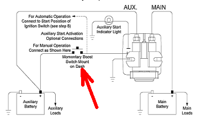
Did you wire up the optional manual control? That might provide a means to connect the batteries together for testing purposes (without having to install a wire across the terminals).

1698681185834.png

A couple of voltmeters, one on each battery will readily confirm the function of the isolator along with whatever charging sources you're using. As far as charge current from the alternator to the house battery, that will be driven by wire gauge, length, connections and battery state of charge. A battery that's above 80% SOC will draw relatively little current at ~14.4V so if that's the only problem, the system might be working as designed. From there you could test it by discharging the house battery say below 50% and seeing what the alternator throws at it.

Mark B.
Albuquerque, NM
 
After getting support from Eaton: It seems the reason why the Eaton/Sure Power 1315-200 battery separator was not closing (or randomly closing) was a poor contact at the ground blade terminal.
The separator needs a clean ground (and common with the 2 banks) to operate.
Now I get 350W charge from the main bank when the relay closes.
I hope this may help other reader to troubleshoot similar issues.
 
PS: Thanks for the helpful comments!
PPS: Watch this good 1315-200 Isolator setup youtube video.
I recommend to install the on/off switch on the ground (5:37 min) for 2 benefits:
- prevents the battery connect solenoid to be always energized when aux batteries being charged.
- Prevent the alternator wearing to charge while driving when you don't need/want to. (in addition to benefits listed on the video)
 
Back
Top Bottom