conversationalonion
Active member
Caveat emptor: I work with a lot of professional trades and access to accurate information is a lot easier for me. No warranty is expressed here just some basic information to hopefully dispel common myths. If you break it, you get to keep both halves. If you want/need this type of hookup on a permanent basis or are not comfortable with this type of DIY, hire a professional. Most (all?!) of us have a good deal of hard earned $$ invested in our RV’s, the amount for it to be done right is well worth it.
seeing as I’m a full timer who often is camped out at my job site, I saw it fit to come up with an adapter solution to allow me to connect to various power sources depending on availability. This often means a FOUR prong (very important the four prong here) residential dryer outlet. This outlet provides 240VAC with ground at 30 Amps using two 120V “hot” leads (generally black and red) one neutral or “return“ lead (generally white) and an earth ground lead (generally green or bare copper). Wire gauges vary but if proper will never be less than 10AWG.
To be clear here there are a few things to note in this set up—
This is *NOT* for a three prong dryer outlet where the neutral and earth ground are bonded (this risks a hot ground in t event of a fault putting the RV electrical system at risk).
All wire, housing components, and receptacles are rated for 30 Amps minimum (in this case 10AWG wire as my length is very short).
As this pigtail will be indoors I was not overly concerned with outdoor cable or any such weatherproofing.
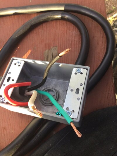
While I forgot to snap a picture (will do so later) the earth ground is tied to the receptacle box and my temporary “cap” of electrical tape over the second hot leg (red wire) was replaced with a proper wire nut after testing.
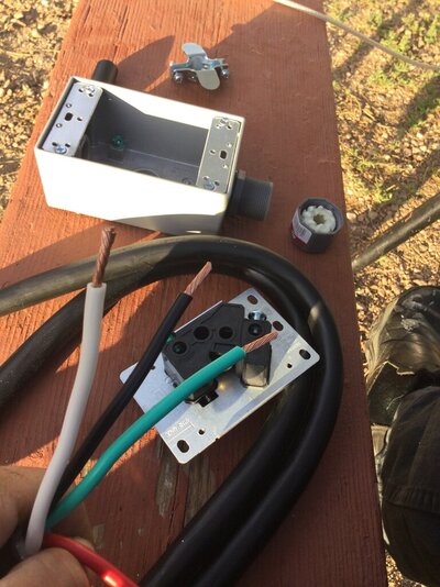
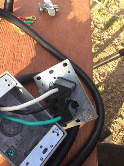
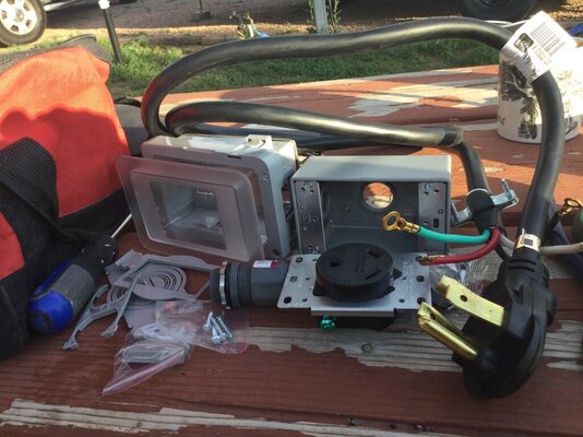
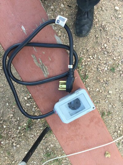
The build is quite simple using a 4 prong 30A dryer plug, an L5-30TT receptacle, a good single gang box and cover, and a waterproof strain relief. Black (120 hot) to hot terminal (brass screw), white (neutral) to neutral terminal (in this case labeled even), and green (ground) to ground terminal with a jumper to the ground lug on the box during final assembly. Everything shored up I tested continuity between terminals to make sure I had no shorts and sealed it up tight.
I’ll answer the first question straight away.... “why didn’t you utilize the other 120 hot leg (red) for a second 20 or 30 amp circuit?” Simple, each wire in the circuit is generally rated for 30 amps *including* the return/neutral, this creates a possible overload on the return should amp draw across both hot legs exceed 30 amps. Because I cannot guarantee what I will find as far as wiring/breaker set up from site to site it’s better to play it safe.
so on to the images:
seeing as I’m a full timer who often is camped out at my job site, I saw it fit to come up with an adapter solution to allow me to connect to various power sources depending on availability. This often means a FOUR prong (very important the four prong here) residential dryer outlet. This outlet provides 240VAC with ground at 30 Amps using two 120V “hot” leads (generally black and red) one neutral or “return“ lead (generally white) and an earth ground lead (generally green or bare copper). Wire gauges vary but if proper will never be less than 10AWG.
To be clear here there are a few things to note in this set up—
This is *NOT* for a three prong dryer outlet where the neutral and earth ground are bonded (this risks a hot ground in t event of a fault putting the RV electrical system at risk).
All wire, housing components, and receptacles are rated for 30 Amps minimum (in this case 10AWG wire as my length is very short).
As this pigtail will be indoors I was not overly concerned with outdoor cable or any such weatherproofing.
While I forgot to snap a picture (will do so later) the earth ground is tied to the receptacle box and my temporary “cap” of electrical tape over the second hot leg (red wire) was replaced with a proper wire nut after testing.
The build is quite simple using a 4 prong 30A dryer plug, an L5-30TT receptacle, a good single gang box and cover, and a waterproof strain relief. Black (120 hot) to hot terminal (brass screw), white (neutral) to neutral terminal (in this case labeled even), and green (ground) to ground terminal with a jumper to the ground lug on the box during final assembly. Everything shored up I tested continuity between terminals to make sure I had no shorts and sealed it up tight.
I’ll answer the first question straight away.... “why didn’t you utilize the other 120 hot leg (red) for a second 20 or 30 amp circuit?” Simple, each wire in the circuit is generally rated for 30 amps *including* the return/neutral, this creates a possible overload on the return should amp draw across both hot legs exceed 30 amps. Because I cannot guarantee what I will find as far as wiring/breaker set up from site to site it’s better to play it safe.
so on to the images:
Attachments
-
 428801B2-60FE-43CD-8BC8-81FD653B968C.jpeg122 KB · Views: 5
 -
 CE45D9EA-54E3-4495-BB70-4D7817CDF0CC.jpeg155.5 KB · Views: 5
 -
 FD557848-81D3-4C6B-9422-5ACAD21F6A52.jpeg159.2 KB · Views: 6
 -
 A285213D-9449-4634-8E8B-9DB4199D2E66.jpeg152.2 KB · Views: 5
 -
 4B12AB65-BD26-4C41-BCC6-863F3A72F1D0.jpeg250 KB · Views: 5