DC/AC Inverter Installation

The friendliest place on the web for anyone with an RV or an interest in RVing!
If you have answers, please help by responding to the unanswered posts.
MODIFIED PLYWOOD WALL

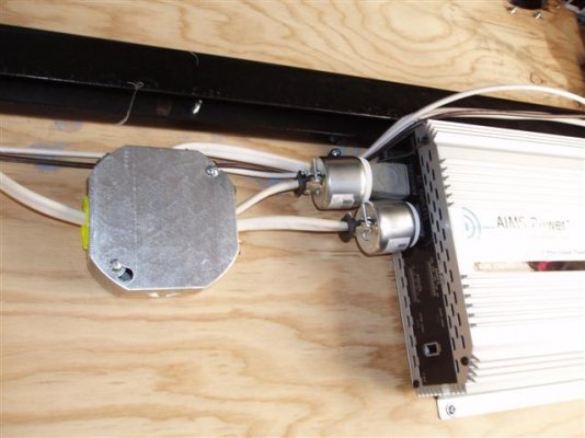
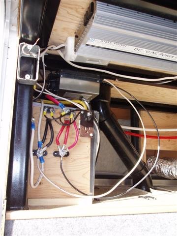
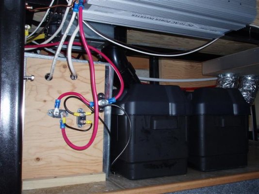
I made the plywood wall much smaller to accommodate the two new battery boxes. I wanted to locate the boxes side by side, but had to settle for back to back, because of the toilet down-pipe. I relocated the DC converter to the ceiling over the factory battery box. The DC/AC Inverter was mounted to the ceiling, close the tie box containing the 12ga Romex from the relay. The wiring on the new wall is only temporary, for testing the unit. I plan to replace all the 4ga stranded factory wire, with 4ga battery cable. I will solder the terminals to the ends of the new cable, this combined with the lower resistance of the battery cable wire, will allow more power to run the air conditioner. I have ordered a new 12 volt, 6 position ATC fuse distribution block. In addition, I have ordered 20 and 30 amp thermal ATC circuit breakers. The Buzzman Shortstop circuit breakers are the modified reset type, if tripped, the only way to reset is to remove power; This would require me to disconnect all four of the batteries. The thermal ATC type will reset themselves, after they cool down. With only two batteries installed to date, I could not test the air conditioner. I opted for a test of my Husky 1.5 gallon, 120 volt air compressor. When I plugged the unit in and turned on the inverter, the compressor quickly came to life and only shut off after reaching 120 PSI. The test was a success, according to the current meter on the DC/AC Inverter, approximately 80 DC amps was required to run the compressor.
 

Attachments

  • DC-AC Inverter Install 003 (Small).jpg
    DC-AC Inverter Install 003 (Small).jpg
    58.2 KB · Views: 22
Just out of curiousity, how much actual difference in ohms is there between #4 cu battery cable and #4 cu stranded cable? #4 cu stranded has a DC resistance of 0.308 ohm/kft. What is it for battery cable?
 
Paul,
For all practical purposes, there is no difference between the two for DC and AC at normal frequencies. When talking about much higher frequencies, the skin effect comes into play where electric current travels near the 'skin' of the conductor. Then, a solid wire can, and sometimes is, replaced by a hollow copper tube of the appropriate diameter. A good explanation of it can be found HERE . BTW, the resistance of #4 wire is .2485 ohms/kft. ;)
 
janpaul said:
Just out of curiousity, how much actual difference in ohms is there between #4 cu battery cable and #4 cu stranded cable? #4 cu stranded has a DC resistance of 0.308 ohm/kft. What is it for battery cable?

I don't know. I know on FACT, the cables I will manufacture will offer less resistance than the ones Sunnybrook installed. Also, when the wires in the circuit are typically carrying 150 amps, I don't want any crimped terminal ends. When you are operating a device that has 10 to 1 current ratio, approximately 10 amps DC in to produce 1 amp AC out, you need all the help you can get!
 
Karl, what is your reference for the values you gave? I looked in NEC table 8 conductor properties.

BN, how long will it be carrying 150 amps? Crimped ends are fine if you have the proper tool to apply the correct pressure such as a hydraulic set. Also, remember that heat (ambient temperature) must be accounted for and the cable will need to be de-rated if you will be in extreme heat conditions depending on where you travel.
 
DC/AC INVERTER OUTPUT

The DC/AC Inverter has a one duplex parallel out. Neither of the individual outlets can power the air conditioner by itself, they are only rated at 12.5 amps each. I wired two general purpose plugs rated at 15 amps at 120 volts. Also coming out of the side of the tie box, is one 12/2 w/gnd Romex wire, this feeds a 20 amp single receptacle at the storage bay door. The duplex outlet's receptacles were two close together for my plugs, luckily I had a ground plug adapter, or I would have had to cancel the test. The current rating for the air compressor tested is 8 amps, the DC/AC Inverter's DC input ammeter registered approximately 80 amps, proving the 10 to 1 current ratio required by the Inverter. This larger input current requirement is the main reason I decided to replace the existing 4ga wire with battery cable wire with soldered terminals. When the air conditioner is hooked up, the DC input current will be around 150 amps. With that much current, not to mention a surge current about 200 amps, the extra expense of the wire is definitely in order.
 

Attachments

  • DC-AC Inverter Install 005 (Small).jpg
    DC-AC Inverter Install 005 (Small).jpg
    48.2 KB · Views: 23
WEATHER DELAY

--------------------------------------------------------------------------------
The will be a slight, hopefully slight, delay to any future responses by me. We live at the Tampa Bay Golf community on the 8th fairway. Christmas day, around 11:30AM, a tornado touched down right behind our home. We were very lucky to have only suffered minor damage; some of our neighbors weren't so lucky.
 

Attachments

  • TB Twister (Small).jpg
    TB Twister (Small).jpg
    53.9 KB · Views: 19
Unlucky to get hit at all but lucky it was a "near miss" rather than dead on.  There were tornado warnings up our way too (Ocala area) all yesterday afternoon but no strikes.  We are kind of on the fringe of "tornado alley", but do get one once in awhile.
 
Wow, That had to be a little frightening! Glad it missed you :)

Back to the inverter subject, I recently bought a couple of 15A plugs that would probably solve your problem of not being able to plug two of them in side-by-side without using an adapter (I hate those things.) Got them at Home Depot. They're Pass and Seymour, a well respected name in electrical equipment. Two fit nicely with room to spare.
 

Attachments

  • DSCN0011.jpg
    DSCN0011.jpg
    29.3 KB · Views: 24
  • DSCN0012.jpg
    DSCN0012.jpg
    21.5 KB · Views: 21
HURRICANES vs TORNADOS

Thank you all for your good wishes. We retired to Florida in 1994. We have had our share of Hurricanes in that time. In 2004 this area was hit by FIVE. Again, that year we were lucky, we were enjoying beautiful weather in Nevada in our Jayco; we missed all five. Of all the hurricanes I've experienced, nothing compared to this Tornado. I was in my lanai checking for leaks when it came by, the loud sound the wind made I will NEVER forget; I thought it was the end! The storm was heading east, just 100 FEET from our home is where the carnage started. Luckily no one was seriously hurt. The one positive out of this is all the publicity. This morning, the insurance companies were about like duckies pouncing on June bugs! One other positive has to be the response of the Pasco County emergency services, in a word they are TERRIFIC!!
 
Venting Hydrogen Gas from new Battery Boxes

--------------------------------------------------------------------------------

At the bottom of the text I have put two links to show what's available for venting batteries. I personally think the PPLMotorhome's is overkill, can you imagine drilling that large of a hole is the side of your RV? In the plastic bag resting on the battery box cover on the right, is a small plastic bag that contains two brass inserts, these are used with plastic hose and 3/8 inch compression fittings. I have drilled a 1/4" hole in the top of each cover and cemented the brass inserts in with Liquid Nails. The OD of the insert is 1/4 inch, the ID of the vinyl hose is 3/16 inch. I immersed the end of the smaller diameter hose in hot water, to soften it up and facilitate it slipping over the larger diameter insert. I did this so when I periodically remove the covers to check the water, the hoses will stay put. Likewise, in the back of the factory vented battery box, I have cemented two more of these inserts. In the latter steps, I will again soften up the hose and slip over these two inserts.

Battery Boxes Vented for Sale
Moroso NHRA Legal Sealed Battery Box [MOR-74050] - $105.95
 

Attachments

  • DC-AC Inverter Install 006 (Small).jpg
    DC-AC Inverter Install 006 (Small).jpg
    48.6 KB · Views: 22
Plywood Wall Shaping Up

--------------------------------------------------------------------------------

In this photo, the modified plywood wall is starting to look good. The two house batteries have their new cables, with soldered terminals, installed at the tie point. Likewise, the two new batteries will have the same set-up. When the tie points are finished, there will be 12 cables, two for each battery and 4 for the Inverter. Each input to the Inverter will have two cables each. In this fashion, when the surge is needed to start the air conditioner, the wires will be able to handle the load. At the top of the board are the two Buzzman Shortstop breakers, this is temporary. I have not yet received the new parts I ordered over the Internet. People who do their own electrical work will want to check out the link at the bottom of the text. Del City has good prices, the only negative is a $25.00 minimum. The white and black wire from the DC Converter are also temporary. I reallocated the AC supply for the DC Converter to the plywood board. I was concerned the unit's plug hanging from the ceiling, may someday work itself loose. All the wires in the picture that still have the blue plastic on them, are from the factory wiring and only need to have their terminals soldered. I wasn't real happy with the DC/AC Inverter's (output) 15A/120V AC plugs. I removed the output wiring, turned the unit 180 degrees and remounted it back on the ceiling. I have to get two "slimmer" plugs that will fit the Inverter's receptacle. I will then tie this output to the single 20A receptacle by the door.

https://www.delcity.net/
 

Attachments

  • DC-AC Inverter Install 008 (Small).jpg
    DC-AC Inverter Install 008 (Small).jpg
    43.7 KB · Views: 23
Hello, I'm following this thread, but my problem is opening the pictures. I can open the ones Karl has fine but the ones from BNTorsney look like finger paintings! Does anyone know whats going on here!!

Thanks Randy
 
Looks like your project is coming along well. Thanks for the nice photos and clear descriptions - I'm sure others will find it instructive.

Randy: your problem viewing pictures is probably one of screen resolution, i.e. your screen is not properly displaying the resolution of some of the pictures. Try fiddling with the display settings of whatever software you are using for photos - or maybe for your monitor itself.
 

Latest posts

Forum statistics

Threads
131,929
Posts
1,387,695
Members
137,678
Latest member
David W.
Back
Top Bottom