Esco 50amp automatic transfer switch not working after replacing.

The friendliest place on the web for anyone with an RV or an interest in RVing!
If you have answers, please help by responding to the unanswered posts.

3rd Gen Army

Member
Joined
May 4, 2021
Posts
6
Location
Hinesville, GA
Mostly in great shape, but a few issues so far - generator was running rough and kept shutting off. I serviced it with new plugs, fuel filter and fuel pump, complete oil change and filter, and cleaned air filter area and changed it. Ran great. Hooked to shore power to conserve gas. Didn't have hot water, found out the anode was completely gone, cleaned tank of all the sediment and a new rod, have hot water.
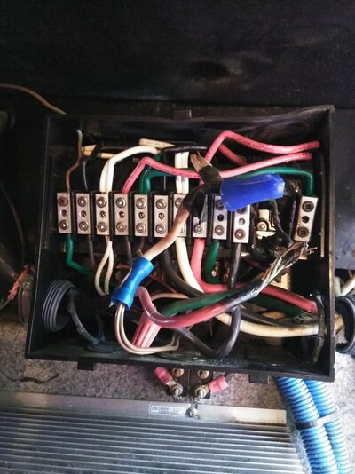
Then the major problem showed up. Went to sleep and woke up sweating, figured we blew a fuse, went back to sleep. Woke up in the morning and checked, nope - our ITS-50R automatic transfer switch had burnt wires and melted completely in several areas. Ok, called a mobile service guy out. He didn't seem to know what he was talking about. I have a 50amp, 120, 240 switch. He told me I only had to have a 50 amp, 120v switch, I didn't need the 240v. I have 2 air conditioners and a washer/dryer. He argued and said I didn't need it, my cord was only 110v. Never saw a cord with a 2 inch diameter and 4 prongs. It has adapter's to go down to 110v. Having been in the Army as a mechanic, I also learned how to work on generators from necessity while in Iraq from 2002-2003. I've also learned electrical repair on my own. I've never been afraid to tackle anything. Besides, I have Google search.
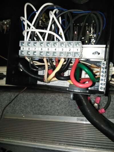
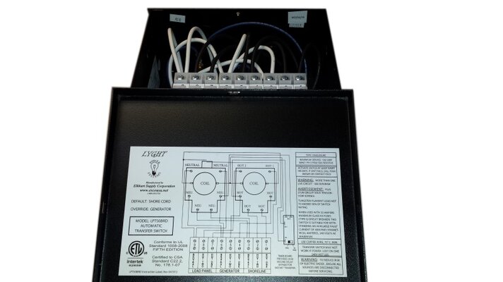
I heard back from the mobile repair, still said I didn't need the 240v and it would be $300 for the switch, plus the call of $75 and the diagnostic of $75, plus putting it in. So I found one for $230. I ordered it and put it in. I have it all hooked up but no power to the coach from shore power or the generator. I've checked my fuses and the wiring, seems like it's correct, so turning to you all for some much needed advice.
What do I need to check to get it working? There are so many fuses and I don't know if I'm missing anything.
I have the normal black, white, red, and green wires for the shore power and the generator, but the coach has two sets of wires that are black, white and ground. I placed the two black wires together and the two white wires together and attached the two ground wires separately.
What do I need to do?
 
It would help if you mention which rig you have, make-model-age, but in general "50 amp" RVs do not use 240V, as such, though there might be a rare exception, so that service guy was likely correct about the 240V not being used on your rig. Normally it is, instead, divided into two 120V legs of 50 amps each. Those 4 prongs are normal for an RV 50 amp connection. And those adapter to take it down to a house-type receptacle are handy on occasion, but it's all 120V unless you have a very unusual rig.

Tell us what your rig is and some folks should be by soon who can provide more help on your problem than I can.
 
Thanks, I did for
It would help if you mention which rig you have, make-model-age, but in general "50 amp" RVs do not use 240V, as such, though there might be a rare exception, so that service guy was likely correct about the 240V not being used on your rig. Normally it is, instead, divided into two 120V legs of 50 amps each. Those 4 prongs are normal for an RV 50 amp connection. And those adapter to take it down to a house-type receptacle are handy on occasion, but it's all 120V unless you have a very unusual rig.

Tell us what your rig is and some folks should be by soon who can provide more help on your problem than I can.
 
Thanks, I did forget to post that. 1997 Newmar Kountry Star. I replaced the Iota Its-50r after it's meltdown.
Thanks for explaining about the 240/120, that makes sense, but the way he tried to explain it didn't.
This is my setup on the Esco. 1-3, shore, 4-6, generator, 7-9 coach. The coach has two sets of wires so placed both white in 9 and both black to 8, nothing in 7, all ground wires are on the right including the only green ground, the rest are coper.
 

Attachments

  • IMG_20210505_102126.jpg
    IMG_20210505_102126.jpg
    137.4 KB · Views: 12
Regardless of whether your RV actually uses any 240v, the 50A shore power service arrives as 4-wire 240v service and the transfer switch has to handle that. And the load center (breaker panel) is also designed to handle the 4-wire, 240v input, even if there are no actual 240v breakers installed in it.
 
This is my setup on the Esco. 1-3, shore, 4-6, generator, 7-9 coach. The coach has two sets of wires so placed both white in 9 and both black to 8, nothing in 7, all ground wires are on the right including the only green ground, the rest are coper.
That doesn't look right. The grounds (copper or green) should all go to the ground bus terminals, the bar on the right in the photo. Each set of 3 (shore, generator, coach) should have two black (hot) wires and a single white. [Note: sometimes the hots are a black & a red rather than 2 blacks]. 1-3 are for the incoming shore cord wires, 4-6 are incoming power from the generator, and 7-9 are the output to the load center (breaker panel).

The blacks (or black & red) never go together; neither do any of the whites. Each should be on its own terminal, and there is a proper location for the white in each set of 3. Terminals 3, 6, & 9 are for neutrals.
 

Attachments

  • ESCO ATS.jpg
    ESCO ATS.jpg
    57.1 KB · Views: 8
Last edited:
but the coach has two sets of wires that are black, white and ground. I placed the two black wires together and the two white wires together and attached the two ground wires separately.
That part is confusing. Can't imagine why there are two sets of white wires going to the coach panel, but put the two whites together on the neutral terminal and the blacks each to one of the hot wire terminals. They cannot be together or you only reduce your available power by 50%.
 
That part is confusing. Can't imagine why there are two sets of white wires going to the coach panel, but put the two whites together on the neutral terminal and the blacks each to one of the hot wire terminals. They cannot be together or you only reduce your available power by 50%.
I tried that, one black in 8 and one in 7, both white in 9. No response.
 
That doesn't look right. The grounds (copper or green) should all go to the ground bus terminals, the bar on the right in the photo. Each set of 3 (shore, generator, coach) should have two black (hot) wires and a single white. [Note: sometimes the hots are a black & a red rather than 2 blacks]. 1-3 are for the incoming shore cord wires, 4-6 are incoming power from the generator, and 7-9 are the output to the load center (breaker panel).

The blacks (or black & red) never go together; neither do any of the whites. Each should be on its own terminal, and there is a proper location for the white in each set of 3. Terminals 3, 6, & 9 are for neutrals.
I don't have a place for the two black and white from the coach. Everything else is as it states and no electricity to coach.
 
I have the same ESCO
ATS that I installed years ago to replace the integrated one in a failed " source Manager" ( Fleetwoods term for an integrated inverter/converter/ATS system )..
Most of the problems with an ATS is the failure to tighten the terminal screws enough to prevent heat build up at the terminals,, Winnebago has had problems in this area and it forced a recall due to fire danger..>>>Dan
 
How the RV automatic transfer switch works. Typically, the wiring diagram of a typical RV switch shows you a three-way switch consisting of one output port and two input ports. The Motorhome switch prioritizes power coming from the generator. A logic-controlled sensor will trigger the device to draw power from one source to another. When the controller detects the generator at the optimum 120 volts, the ATS switches back to the generator input. Meanwhile, the switch disconnects from the onshore power supply.
 
How the RV automatic transfer switch works. Typically, the wiring diagram of a typical RV switch shows you a three-way switch consisting of one output port and two input ports. The Motorhome switch prioritizes power coming from the generator. A logic-controlled sensor will trigger the device to draw power from one source to another. When the controller detects the generator at the optimum 120 volts, the ATS switches back to the generator input. Meanwhile, the switch disconnects from the onshore power supply.
Not only does it simplify the process of drawing energy from a pedestal or external power source and the onboard generator. It also makes it safer to do so.
 
Back
Top Bottom