Onan RV GQ 4000 plug wires chewed

The friendliest place on the web for anyone with an RV or an interest in RVing!
If you have answers, please help by responding to the unanswered posts.
If Onan sent you those drawings per the serial number of you unit, then go by them. If you go back to my post #7, the first drawing (labeled 10-1 on the bottom), you'll notice the same type of drawing as yours on post #20. On my post, the pin to A1 is J12 and on yours J11.

The second drawing (10-2) looks like a detailed drawing of 10-1. But here, they show a jumper connector before the A1 board.

Do you have the more detailed drawing like the one I gave you?
I have the 144 page file that is used by the people building the generators.
 
If Onan sent you those drawings per the serial number of you unit, then go by them. If you go back to my post #7, the first drawing (labeled 10-1 on the bottom), you'll notice the same type of drawing as yours on post #20. On my post, the pin to A1 is J12 and on yours J11.

The second drawing (10-2) looks like a detailed drawing of 10-1. But here, they show a jumper connector before the A1 board.

Do you have the more detailed drawing like the one I gave you?
Your drawing is 611-1194 and your marked up drawing says pin 8 on A1


Mine is 611-1267 which is what my model# says to use.
My drawing shows pin 11 on A1

If I have to I can put a switch on the remote panel to turn the solenoid on and off.
I have not plans of pulling the generator out. Plus not sure I trust they wired it per schematic as I already found one wire going to remote not matching there drawing I can only assume the harness going to the remote start was not done correctly . At least it was only 4 wires and obvious what was wrong.
 
If Onan sent you those drawings per the serial number of you unit, then go by them. If you go back to my post #7, the first drawing (labeled 10-1 on the bottom), you'll notice the same type of drawing as yours on post #20. On my post, the pin to A1 is J12 and on yours J11.

The second drawing (10-2) looks like a detailed drawing of 10-1. But here, they show a jumper connector before the A1 board.

Do you have the more detailed drawing like the one I gave you?
So I pulled the A1 board and took the plug loose. I found the wire that was marked J1-11 as my drawing said. As I was pulling lightly on it a wire on the other side of the wall was moving. So I pulled on it at the end and sure enough there it was. Thinking back I should have pulled on all those wires when looking up the loom. I was expecting it to be cut at my end but it must have left the loom farther up where it was connected to the chewed wire.
Skip to the end and I tested it with those to ends attached to each other it started right up.
Starts from the remote switch and the hour meter is working. I have a whole 6 hours on it since 2016.

Thank you for all your help.

Gary
 
I'm glad I was of some help and most of all that you fixed your issue. Really appreciate it that you came back on here and let the forum know the outcome.

Sometimes good people on here provide help and never hear back. G(y)ood for you.
 
I'm glad I was of some help and most of all that you fixed your issue. Really appreciate it that you came back on here and let the forum know the outcome.

Sometimes good people on here provide help and never hear back. G(y)ood for you.
The wires to the remote start was pretty easy but finding the single wire was a pain. Your idea of going the A1 connection and working back worked perfect. I had looked at the wires in the loom where it was at but I was expecting it would have been cut at the end I had access to. Not the other end. But it makes sense from where I had seen pictures of where it looped back to the solenoid.
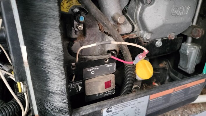
Here it is all soldered together with heat shrink which I finished shrinking after the photo.
 

Attachments

  • P1-11 E3.jpg
    P1-11 E3.jpg
    116.3 KB · Views: 4
Good deal. This is what I use for rodents in my home and vehicles. Now that the weather is going to get cool in a few months, the rodents will want a warm place to nest.

I loop a wire through the middle hole and place a couple under the hood of my truck and tie them down. I check for the chewing marks on them and that tells me the are eating poison instead of wires - so far so good

I am thinking of maybe some of the electronic ones that create a sound they are supposed to hate plus a flashing light.
These rodents came after they started building on the 2 acres behind us. When you cut down over 80 trees and dig up every inch of land to reshape it you are bound to get new guest.
When this started we had a family of 7 skunks living under our deck.
Anyway I sure feel good getting the generator fixed as we are getting ready for a short trip and it is still hot around here.
 

Latest posts

Members online

Forum statistics

Threads
131,954
Posts
1,388,153
Members
137,708
Latest member
7mark7
Back
Top Bottom