Please: Request for final systems check before energizing.

The friendliest place on the web for anyone with an RV or an interest in RVing!
If you have answers, please help by responding to the unanswered posts.

chaostactics

Well-known member
Joined
Jul 8, 2022
Posts
223
Location
Maryland
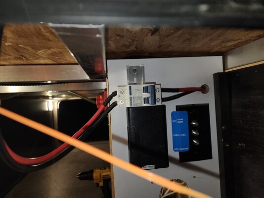
Still on to do list:
1. Run ground from MPPT to Multiplus ground.
2. Mount MPPT to wall.
3. Enclose solar breaker/disconnect in breaker box.
4. Bolt Multiplus ground to frame.
5. Put back on all covers
6. Attach smart shunt wire to + batt terminal.
7. Mark red AC out wire green.
8. Put 30 amp breaker between shore power and Multiplus
9. Get better caps for battery terminals (can anyone recommend where I can find some.

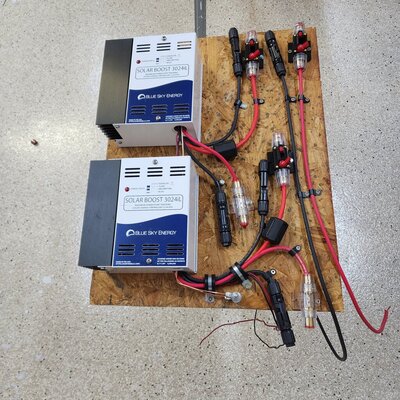
Notes: MPPT is set to 7 on the dial for Lifepo batteries thank you for the reminder @solarman

All wire is multi strand wire, all wire ends either have lugs or ferrules, none of the wires are pulled taught all wires have play in them.

There is a 300A MRBF fuse on the + battery terminal. I am carrying spares of all fuses and an extra pair of 80A fuses Incase the 60A fuse is not good enough for the 800W of solar in parallel.

All wire is 2/0 or 6 awg with the exception of the wires going into the MPPT from the panels which is 10 AWG factory wire.

Solar disconnect/breaker is 1000V / 63A

20230206_183330.jpg
20230206_183337.jpg
20230206_183343.jpg20230206_183406.jpg
 

Attachments

  • 20230206_183603.jpg
    20230206_183603.jpg
    101.5 KB · Views: 6
The only thing I don't see is a Class T fuse in case of catastrophic short and the BMS fails to disconnect. All the fuses I see are MEGA fuses which will not self extinguish an arc from an LiFePo4 battery due to its low internal resistance, these are fine for protecting downstream branch wiring as long as there is a proper size Class T fuse upstream.

p.s. for terminal cable covers these are the ones I used https://smile.amazon.com/gp/product/B08RJ2SHKY/ the price has went up about $2 since I bought them in 2021
 
Make yourself a list for power up-sequence and then a power-down sequence. Verify one thing at a time before powering up the next thing.

Example; do not connect or turn on any 120 VAC until you verify the solar system. Connect solar controller to battery first, then connect solar panels. Are the panels charging the battery. Next, verify inverter is making 2000 W of VAC (leave the pedestal power off), use a hair dryer or equivalent.

Anyway, you get my drift.
 
@Isaac-1 Theres a 300A MRBF on the positive battery terminal between the terminal and positive cable.
20230206_201055.jpg

@Pedro Dog you wouldn't happen to have one of those lists saved on your phone/tablet/computer would you?

Thank you both so much for your feedback!
 
A Class T fuse has about 4 times the interupting ability vs the MRBF, which is somewhat marginal in its ability to extinguish an arc in a 12V LiFePo4 battery. I personally would prefer that added safety factor.

I believe you will have an AIC of about 5000 with that MRBF vs 20,000 with a class T fuse. From what I have read one should have a minimum AIC of 5000 for a typical 12V LiFePo4 battery.

p.s. correction the MRBF has an AIC of 10,000, which is still half of what the Class T fuse will have, but is probably enough for a 12V LiFePo4, which could possibly exceed 10,000 amps, but is somewhat unlikely to in real world situations with a single 100AH battery, but it is not enough for a 24V LiFePo4
 
Last edited:
@Pedro Dog you wouldn't happen to have one of those lists saved on your phone/tablet/computer would you?

I don't but I made some simple instructions with my printer and laminated them and taped them next to the controller. Maybe HueyPilotVN does, he has the mother of all solar systems. He's right about connecting the controller to the battery first, then the panels. Then when shutting down, disconnect solar panels first then isolate the battery.

I am very instructions oriented, as a retired electrical engineer that spent a career in development and testing, I've smoked plenty of circuits. Nothing smells worse than burnt wire insulation.
 
Last edited:
On the subject of connecting the battery to the controller first I would like to recommend the following.

I am a kind of belt and suspenders guy, and I wanted a quick, easy and safe way to disconnect the solar panels from the charge controllers.

My solution was to use an inexpensive combination fuse and circuit breaker inline with the input to the charge controller.

By simply pushing the red button you can disconnect the solar panels from the controller without taking out the wire. You can reconnect the panels by turning the red switch.

You still need to connect the battery first when connecting and last when disconnecting.

I have four charge controllers in my system, and I wanted to gather data on exactly how much current each of the systems was passing thru. The monitor would show the total but I wanted an easy way to measure the effect of turning off individual panel sets.

I also put a simple fuse on the output but that is just me being me.

Here is a picture of what I am posting about. It is not nearly as neat or organized as your layout, but it is functional for testing performance data.

Here is a link to what I used for the input side.

Amazon.com: 50Amp Audio Circuit Breaker Auto Car Stereo Inline Fuse Holders Inverter, Manual Reset 12V-24V DC for Automotive Marine Boat Audio System Protection (50A) : Automotive
 

Attachments

  • 20220917_182108.jpg
    20220917_182108.jpg
    318 KB · Views: 8
@HueyPilotVN

Already taken care of (I do need to put it in an enclosure that's coming tomorrow.


20230206_183603.jpg

The output is fused in the Victon Lynx distributor/bus bar

PS I let you "bully me" 😆 into adding a 30 A breaker between the shore power and Multiplus. I can bring it up through the bottom of my pantry and have the breaker you suggested plus an enclosure coming tomorrow as well.

I'll get it installed before plugging into shore power for the first time.
 
I am very instructions oriented, as a retired electrical engineer that spent a career in development and testing, I've smoked plenty of circuits. Nothing smells worse than burnt wire insulation.
Burnt differential lube, burnt transmission fluid, oh, and that gunk that accumulates at the bottom of the grease trap in the shop floor. :whistle:
 
I finally have time to work on the electric system.

I understand the breaker between shore power and multiplus, and breaker/solar shut off between panels and MPPT. Someone had mentioned putting between the multiplus and main panel. That one I don't understand as the main panel already has a main breaker.

Any input on that last one?
 
Almost a year later and I'm considering finishing this. I'm still unclear on the extra breakers. Which is sorta why this ended up moth balled in the first place
 
You do not really need the 30 amp breaker between the invertor output and the main panel breaker.

Just me with my belt and suspenders approach. My breakers are within reach of the bed in case of fire,

Kind of ironic, given that it burned down, because of the fridge.
 
Regarding extra breakers (And in some cases fuses) A good idea if you can is to draw it out on paper (or computer) and post the diagram..

Sometimes there is a reason for it.. I had a radio stop working a couple weeks ago (Total cost of repair was in the 5¢ Range. Soldered a connection (less than five cents actually)
Power for this radio is "Battery Direct" There is a 40 amp fuse in the positive lead 10 ga wire from there to a power distribution panel a 2nd 40 amp fuse on the input connection.

A 25 amp branch feeds the "Extion cable" to the radio. that's a pair of Blade Fuse inline connectors (That's all just the factory leads) anderson power poles at the feed point to the distribution panel and of course the "Outlet" to the radio and both ends of the "extension" cable 20 amp in the Positive I think 25 or 30 in the negative... One of the extension leads came loose at the connector.

My Little Friend (Pocket VOM from Radio Shack) found it swiftly

Why all the fuses.
One at the battery protects the line to the inside. If it shorts pop goes the fuse. The Distribution panel is a commercial and like all commercial it has a "Main" (40 amp) and "Branch" fuses.

The radio.. Well during testing I tried feeding it Direct (Bypassing the panel) You can do that with Anderson power pole connetors.... the fuse in the negative is in case something goes KaKa in car and the starter tries to return to the battery via the radio.. No way that ground lead fuse will take that kind of current but the radio chassis and coax for a short time.. No tribble at all.
 

Latest posts

Forum statistics

Threads
131,928
Posts
1,387,649
Members
137,676
Latest member
traxster
Back
Top Bottom