Ray-IN
Well-known member
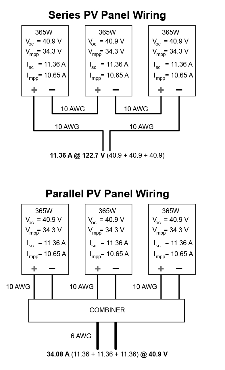
On the winnieowners.com website, every thinks just because Winnebago used 10 ga. AWG wire in their solar-prep package, it is the correct size for all solar arrays, a 30A solar panel system is what they are using, I said 10 AWG is too small for a 30A solar system, but that is me just reciting what I've read.
Anyone interested might go visit and state the facts.
Anyone interested might go visit and state the facts.