CharlesinGA
Well-known member
From what I can figure out on the PD website, the Lithium models are single voltage and do not have the charge wizard feature. You would NOT want to use these on non Li batteries. The standard model has a jumper on the circuit board that you can change to adjust it for standard Lead Acid or "gel" batteries (and I think they really mean AGM here, but you would want to call them.) So, yes, you have to pick your batteries and converter together.
Basically this converter IS in its own case, just that there is no front to it. You slide out a metal box, and slide in another one. This IS a universal kit, and the instructions cover many different models and brands. All other power panels require you remove the converter from the steel box and discard the steel box, but in YOUR case, you use it assembled as it comes out of the cardboard box.
Wire size, I would stick with the same amperage, unless you can determine that you have heavy enough wires going to the battery to handle the additional amperage. In my motor home it came with a 55 amp converter and that is what I used, but the Bigfoot came with a 45 amp and 8 gauge wire, so I stuck with 45 amp as I felt the 55 amp needed 6 gauge if the converter were ever called to pump out a full 55 amps.
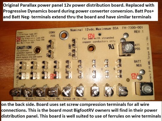
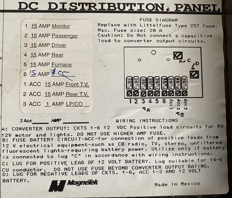
You DO NOT have to use the new fuse panel, but you don't have the added features of the new panel 1) blown fuse indicators, and 2) Ability to manually force the converter to different modes.
The most work is the new fuse panel. It fits perfectly but if your wires are soldered to the old board, you will want to use a soldering gun to remove them from the board and then slip them under the screws at each terminal. On some old Magnetek boards the wires were in screw tight terminals and you simply take then out of the old terminals and put in the new.
The most care that is required is 1) carefully forming the heavy gauge wires to go where you want and not put stress on the large terminals and to make sure the wires are not rubbing on sharp edges, and 2) (this is important) to use an open end wrench (3/8" I think) to hold the large terminal blocks to prevent them from rotating and being ripped off the circuit board as you tighten the screws. Its an old "equal but opposite reaction" kinda thing.
Late EDIT: When connecting the large wires I find it is much safer to do with the board NOT screwed to the mounting. Insert the large wire, gently tighten the screw to hold it in, then take the wrench and hold the terminal block and use the Allen wrench to tighten the setscrew while countering the force with the wrench. This way you don't run the risk of damaging the printed circuit board connections.
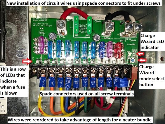
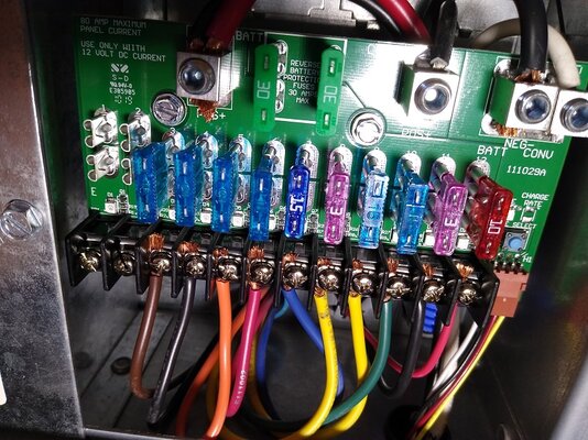
The new circuit board has LEDs at each terminal to indicate a blown fuse, and also has a button and LED to control the charge wizard in the converter (you will never need to mess with this) The purpose of the charge wizard control is to be able to override the charging schedule in the converter. If you are boondocking and want to top the batteries off the generator rather quickly you can use the push button and the LED to force it to Bulk charge mode of 14.4v to bring the batteries up faster. Otherwise depending on the actual state of the batteries, the converter might not go to bulk charge and just charge at 13.6v.
On my motor home installation I ended up re routing a couple of wires thru a different hole in the power panel and using plastic knockout sleeves to protect the wires from the metal edges.
The pic above is from my 2007 motor home, other pics are from my more recent conversion of my 2008 Bigfoot trailer, hence the different color/shade of the fuse panel. You do not need to use the forked spade terminals or ferrules on the wires. I did this after the initial installation to improve the durability of the install.
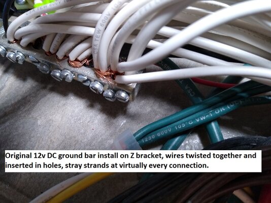
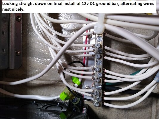
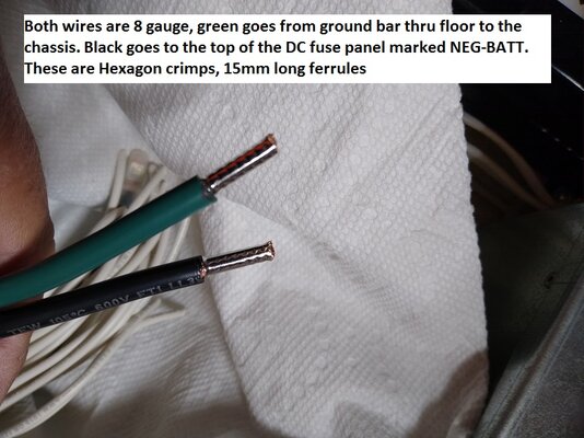
I installed ferrules on the ends of the wires (except where I used the forked spades on the terminal strip) and I did this as a result of finding a lot of flayed wire strands. I bought a ferrule crimper and ended up ordering special ferrules that were longer than the ones that came with the crimpers, and I'll throw in a couple of pics of before and after on my ground bar.
The pics were sized and annotated for a thread I created on the BigfootRV Owners Club Intl discussion forum. Lots of quality lapses in RV manufacture both then and nowdays. Next to the last pic is to show you what wires with ferrules on the ends look like, thin metal sleeves slipped over freshly stripped wire and crimped into place in either a square or hex shape. Ferrules are nice because they are soft and when a screw terminal is tightened up on them they crush slightly and the screw holds them in well but the screw cannot cut the fine wire strands like happens with bare wire inserted in the screw terminals. The wires on the converter are pre stripped and tinned. Small wires fit nicely under the hold down plates on the bottom terminal strip. The very last pic is the fuse panel before I installed the ferrules. I am an aircraft mechanic (was, I retired) and picky enough to go back and re do an already acceptable installation I had previously done. (the factory ground bar install was what started the ferrule installation, it was UN-acceptable).
Charles
Basically this converter IS in its own case, just that there is no front to it. You slide out a metal box, and slide in another one. This IS a universal kit, and the instructions cover many different models and brands. All other power panels require you remove the converter from the steel box and discard the steel box, but in YOUR case, you use it assembled as it comes out of the cardboard box.
Wire size, I would stick with the same amperage, unless you can determine that you have heavy enough wires going to the battery to handle the additional amperage. In my motor home it came with a 55 amp converter and that is what I used, but the Bigfoot came with a 45 amp and 8 gauge wire, so I stuck with 45 amp as I felt the 55 amp needed 6 gauge if the converter were ever called to pump out a full 55 amps.
You DO NOT have to use the new fuse panel, but you don't have the added features of the new panel 1) blown fuse indicators, and 2) Ability to manually force the converter to different modes.
The most work is the new fuse panel. It fits perfectly but if your wires are soldered to the old board, you will want to use a soldering gun to remove them from the board and then slip them under the screws at each terminal. On some old Magnetek boards the wires were in screw tight terminals and you simply take then out of the old terminals and put in the new.
The most care that is required is 1) carefully forming the heavy gauge wires to go where you want and not put stress on the large terminals and to make sure the wires are not rubbing on sharp edges, and 2) (this is important) to use an open end wrench (3/8" I think) to hold the large terminal blocks to prevent them from rotating and being ripped off the circuit board as you tighten the screws. Its an old "equal but opposite reaction" kinda thing.
Late EDIT: When connecting the large wires I find it is much safer to do with the board NOT screwed to the mounting. Insert the large wire, gently tighten the screw to hold it in, then take the wrench and hold the terminal block and use the Allen wrench to tighten the setscrew while countering the force with the wrench. This way you don't run the risk of damaging the printed circuit board connections.
The new circuit board has LEDs at each terminal to indicate a blown fuse, and also has a button and LED to control the charge wizard in the converter (you will never need to mess with this) The purpose of the charge wizard control is to be able to override the charging schedule in the converter. If you are boondocking and want to top the batteries off the generator rather quickly you can use the push button and the LED to force it to Bulk charge mode of 14.4v to bring the batteries up faster. Otherwise depending on the actual state of the batteries, the converter might not go to bulk charge and just charge at 13.6v.
On my motor home installation I ended up re routing a couple of wires thru a different hole in the power panel and using plastic knockout sleeves to protect the wires from the metal edges.
The pic above is from my 2007 motor home, other pics are from my more recent conversion of my 2008 Bigfoot trailer, hence the different color/shade of the fuse panel. You do not need to use the forked spade terminals or ferrules on the wires. I did this after the initial installation to improve the durability of the install.
I installed ferrules on the ends of the wires (except where I used the forked spades on the terminal strip) and I did this as a result of finding a lot of flayed wire strands. I bought a ferrule crimper and ended up ordering special ferrules that were longer than the ones that came with the crimpers, and I'll throw in a couple of pics of before and after on my ground bar.
The pics were sized and annotated for a thread I created on the BigfootRV Owners Club Intl discussion forum. Lots of quality lapses in RV manufacture both then and nowdays. Next to the last pic is to show you what wires with ferrules on the ends look like, thin metal sleeves slipped over freshly stripped wire and crimped into place in either a square or hex shape. Ferrules are nice because they are soft and when a screw terminal is tightened up on them they crush slightly and the screw holds them in well but the screw cannot cut the fine wire strands like happens with bare wire inserted in the screw terminals. The wires on the converter are pre stripped and tinned. Small wires fit nicely under the hold down plates on the bottom terminal strip. The very last pic is the fuse panel before I installed the ferrules. I am an aircraft mechanic (was, I retired) and picky enough to go back and re do an already acceptable installation I had previously done. (the factory ground bar install was what started the ferrule installation, it was UN-acceptable).
Charles
Attachments
-
 Ferrule inst dc fuse panel FINAL version with spade connectors.jpg456.4 KB · Views: 6
 -
 Ferrule inst old parallax DC fuse panel.jpg407.5 KB · Views: 6
 -
 Ferrule inst ground bar before.jpg316.1 KB · Views: 5
 -
 Ferrule inst ground bar inst completed.jpg355 KB · Views: 6
 -
 Ferrule inst ground bar 8 gauge ground wires.jpg307.7 KB · Views: 5
 -
 Ferrule inst dc fuse panel before.jpg394 KB · Views: 5
Last edited:
") until I isolate what is going on.
until I isolate what is going on.