What AWG battery cable gauge to simply connect battery bank in parallel?

The friendliest place on the web for anyone with an RV or an interest in RVing!
If you have answers, please help by responding to the unanswered posts.

Barnibus.convert

New member
Joined
Jun 20, 2021
Posts
3
Location
Oregon
For the life of me, I can't seem to find one single, solitary source on this planet, in our dimension, in this area of space and time in the universe, that will simply tell me what gauge battery cables I need to connect my batteries together in parallel (I believe they're specifically referred to as interconnect cables?). There seems to be no magical combination of keywords I can enter in my search engine to come up with the exact information I need.

There are plenty of sources to help you figure out what size AWG battery cables you need to connect to an inverter, or from "power source to power load", or sources will provide charts I can easily read but never provide information for cables under 15 feet long. If I include the word "parallel" in my search, the ONLY sources that come up just tell me how to connect the batteries in parallel, which I already know. I'll go ahead and click on as many of those sources I can before becoming infuriated to see if even one of them will also provide information on determining the cable gauge, but nope.

I've found "calculators" that will supposedly help me with this, but they're still always aimed at cables meant for something else - not the short little cables you use to connect the darn batteries together. I've found mathematical equations I can supposedly use but then have no idea what to do with the number I end up with (how does 7.whatever tell you the gauge cable you need?). Some sources say I need to determine the gauge of the cables I need by the inverter. Some say, no you use the converter/charger. Some say no, you use your solar panels. I don't see what any of this has to do with simply connecting the batteries themselves together in parallel. No connection is made to that in the sources.

I'm about ready to beat my face into a wall.

Here's what I plan to work with:

Four, 12v 105AH flooded deep cycle batteries.
Intel Power 4500 Series, All-in-One 240V, 50 Amp, AC/DC Distribution Panel with built-in Charge Wizard, 90 Amp (PD4590)
2000W 12V Pure Sine Wave Inverter (Renogy)

I've already got three, 325W solar panels on my roof. Specs:
Max Power: 325W
Open-circuit volt (Voc): 40.40
Short-circuit current: 10.14
Voltage @ PMAX (vmp): 33.65
Current @ PMAX (imp): 9.66
Max system voltage: 1000
Fuse rating: 20

MPPT Charge Controller I plan to get for it: EPEVER Tracer-an Series High-Power
Maximum input current: 100A
Maximum PV input power: 1250W/12V
Maximum input voltage(open circuit voltage): 150V

With this information, can somebody just tell me what gauge cables I need to connect the batteries in parallel? It would probably be best if the cables are 24 inches since my battery bank is going to be on two levels. I want to make sure the lower ones reach the upper ones. As for what gauge cables I'll need for everything else, I'll climb that mountain when I get there.
 
Real simple. Measure out total length you think you need for bothmpos ans neg. Go to any welding supply store and buy the total length of O or OO welding cable you need. An electrical supply house buy enough lugs. Cut, assemble. You will never regret using this stuff. Super flexible and can carry all the current you can handle.
 
The interconnecting wire size should be able to carry the maximum amp draw to the motorhome based on the electrical design.

If a #2 wire is used to feed the motorhome from the batteries, #2 wire should be used to interconnect the bank.
 
Last edited:
Two answers
In your specific case I would suggest 00 (Same as the wire from battery to converter

Absent the inverter. Standard starter cable (Usually 4GA) is what I recommend as it is very easy to find pre-assembled in assorted lengths.
 
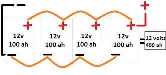
When paralleling batteries, electrically you can just plop another one in the line and off you go, but the subtleties of even very minor differences in cable resistance and battery merit will end up in a net result of less than optimum battery discharging and charging performance over many cycles. Sooo, what you want to do is connect them in such a way that electrically they're in parallel but the cable and battery differences cancel. Hence the diagrams you see such as this one:

images.jpg

The wire gauge then becomes a decision based on how much current you intend to draw. Technically the current through the interconnect cables will be less than what you're drawing from the bank so those cables could be "smaller". Also, since they're pretty short even a small cable will exhibit minimal voltage drop but since there's little practical advantage to critically selecting the least possible size cable, the advice to use whatever gauge is being used for the primary cabling will check all the boxes.

Mark B.
Albuquerque, NM
 
Last edited:
UnboundSolar sells battery banks with the cables that you need to connect the batteries together. They also sell cables separately. I have 6V batteries in series with 2/0 cables between them and #4 cables to my inverter. You can contact them to validate.


I'm just a customer.
 
The interconnecting cables have to carry the same amp load as the mains, so need to be the same AWG. None of those cables will be long enough for length to be a worry, so no need to up-spec the AWG for distance. The AWG depends on that amperage but you should always err of the side of bigger.

Typically the controllers pr chargers have max amp limits between 50A and 120A, so the main cables ought to be size for that unless the battery bank simply cannot deliver that much for more than several seconds. Your converter/charger is 90A and the MPPT 100A, so I'd go with a size that supports a minimum of 100A.
 
As for what gauge cables I'll need for everything else, I'll climb that mountain when I get there.

You've got it backwards, figure out what you'll need for the trailer/RV and then buy extra to make the interconnect cables.

There is no "set size" for these. They need to match the load of the trailer and the amperage of the charger.
 
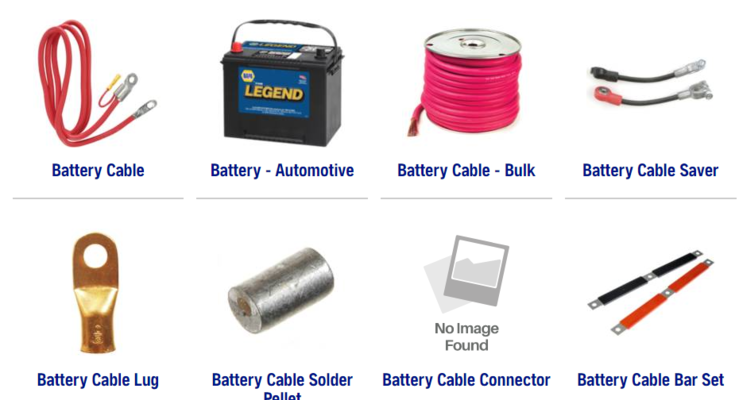
I've used NAPA as a source for this too. Local auto stores should have the connectors and wire in bulk or pre-made. They also have a "shorting bar" that might suit your needs for interconnecting..
1625178326956.png
 
I am running 2/0 Super Excelene ultra-flexible welding cable incased in Slitwrap from the batteries to the inverter and all switches and shunts inbetween, including all of the buss interconnect with the batteries.

People can argue cable size vs. length all day and come up with different answers. But nobody will take issue running 2/0 end to end.

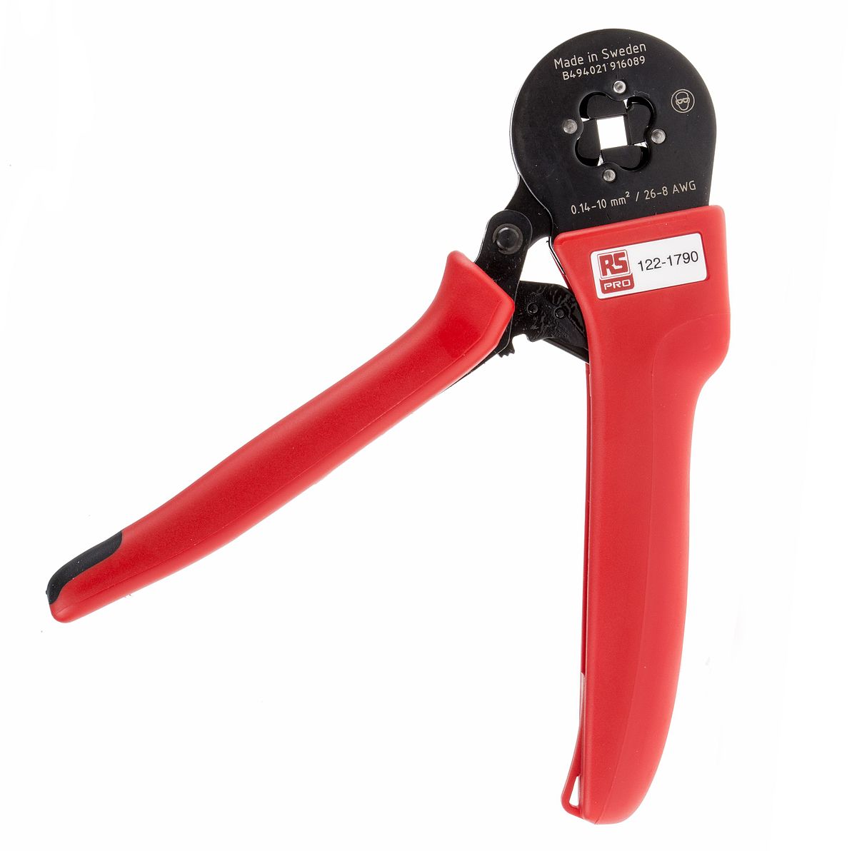
Same goes for the crimps. If you want to be anal about your install, use a real compression crimper, not one of those cheap hammer crimpers. Its not unusual for those cheap crimps to go resistive.

As they say: Buy the Best and Cry Only Once
 
If you are investing this much in cables and hardware I suggest you learn to solder. IMHO crimping a lug onto the end of expensive premium wire is like putting cheap radials on a race car. You can tell right away where the failure point will be.
 
If you are investing this much in cables and hardware I suggest you learn to solder. IMHO crimping a lug onto the end of expensive premium wire is like putting cheap radials on a race car. You can tell right away where the failure point will be.

That may or may not be true.


After doing a fair bit of digging, I cannot find any truly authoritative comparison between the two. Lots of opinions, but nothing verifiably factual.

I have always found a good hot solder joint to be the best. But I've had that questioned.

Anyone KNOW for sure one way or the other?
 
You can poorly solder just as readily as poorly crimp.

From a practical perspective, to heat heavy gauge battery wire hot enough for solder to flow will require a torch, and that amount of heat would surely melt most types of insulation.

What makes crimp favorable over solder is it's consistent as long as you're using the correct dies, less risk of insulation damage and from a reliability standpoint, less likely to suffer fatigue failures. When terminations are soldered, solder will wick up the wire some distance and under motion/vibration, that stiff section won't flex and may fatigue and break.

Solder can be reliable but it takes skill to accomplish the connection. With crimps you trade skill for tooling. On a production floor you can train a guy to use a crimp tool in minutes, same can't be said for soldering.

I've been doing both for decades and if I have the choice, out comes the crimper. Strip, squish, done.

Mark B.
Albuquerque, NM
 
I've been in the electronics repair business for 30+ years. I'm happy that people crimp, I always solder for my own gear but those that crimp make excellent customers 5-10 years later when the crimp has more green fuzz on it than a bad peach.

One big problem is that the DIY'r doesn't usually own a professional grade crimping tool. I've seen lugs put on and squished with pliers or hit with hammers. Like I said - good for business.

PS: I think the winters here in Canada may be a little harder on an outside crimp than in Albequerque.
 
Yep, with the wrong tool you can make a crappy crimp. To adequately assess a process though you have to assume all things equal in terms of fitness of purpose, materials and methods.

A properly done crimp is a gas tight cold weld. It doesn't get better than that for current conduction or environmental reliability. About the only positive I can say about soldering is that it does offer the option of a field repair. It's a tool in the tool box though, if I need it I can use it. But it would be the exception to the rule, even as a home DIY/hobby 99% of what I do is crimped.

Mark B.
Albuquerque, NM
 
If you are investing this much in cables and hardware I suggest you learn to solder. IMHO crimping a lug onto the end of expensive premium wire is like putting cheap radials on a race car. You can tell right away where the failure point will be.
nonsense, it has been proven time after time that a soldered joint for mobile applications is a very bad idea, a properly crimped cable will outlast and out perform a soldered joint, period.
 
You can poorly solder just as readily as poorly crimp.

From a practical perspective, to heat heavy gauge battery wire hot enough for solder to flow will require a torch, and that amount of heat would surely melt most types of insulation.

What makes crimp favorable over solder is it's consistent as long as you're using the correct dies, less risk of insulation damage and from a reliability standpoint, less likely to suffer fatigue failures. When terminations are soldered, solder will wick up the wire some distance and under motion/vibration, that stiff section won't flex and may fatigue and break.

Solder can be reliable but it takes skill to accomplish the connection. With crimps you trade skill for tooling. On a production floor you can train a guy to use a crimp tool in minutes, same can't be said for soldering.

I've been doing both for decades and if I have the choice, out comes the crimper. Strip, squish, done.

Mark B.
Albuquerque, NM
quite correct, as a professional engineer I have public safety to consider. in 40 years I have never specified a soldered joint for mobile use, it's just proven bad practice. for some device in your living room that is not subject to movement or vibration then solder is just fine.. for mobile .. NO
now, there's crimping and DIY. crimps need to use the correct fittings with matching wire gauge and a properly sized crimp jaw. the kind I typically specify are CE certified 16 or 20 ton hydraulic crimpers with CE certified jaws. the CE mark is stamped in the lug on completion. the termination is then covered with a heat shrink sleeve to keep out moisture/dirt etc..
DIY hammer crimpers are the devil's invention, so bad in so many ways, they do not provide consistent reproducible crimps and generally give inadequate bonding and high resistance joints - these are the crimps that fail and overheat, especially with undersized wire and over current conditions.

Mark's diagram above is one of several best practice connection methods. cable sizing is based on three factors.

1) Supply Voltage
2) Load in Watts
3) Distance.

from the supply voltage and load we can calculate the Amperage.
from the wire resistance and Amperage we can calculate the voltage drop
therefore using Ohms law,

Amperage = Watts / Voltage
Voltage drop = Amps x Resistance

just simple 5th grade math.. for ease I suggest an online calculator, if you want all the
calcs then PM me..

we can find the wire resistance vs AWG from NEC tables or do a search on the web.
here is one such table : en.wikipedia.org/wiki/American_wire_gauge

an online calculator : Voltage Drop Calculator
here will automatically use NEC wire tables for you..

using your 2000W inverter as an example
we have a 2000 Watt load, 12V supply and 2 feet distance and under 3% drop.
I will be surprised if you can keep the cables to such a small distance, other physical constraints will
probably push this out to 4 feet. so i'll use 4 feet for the example.

Amps = 2000 Watts / 12 Volts = 166 Amps

using the site above ( ignore power factor and set conduit to PVC ) and 4 feet
we get a wire size of 2 AWG, voltage drop of 0.25 V ( 2%)
this is an ideal condition, in practice I would suggest you go one gauge higher
to ensure the wire temperature at max load will not be excessive.
so 1 AWG is suitable for device and the parallel battery connections.


i would also suggest you have these cables made by a local contractor/weld shop//marine/golf shop.
it really is important to have proper termination with currents as high as this.
if you need tight bends then welding cable is a good choice, but DO have a welding shop make
them for you with the CORRECT matching lugs... welding cable requires specific size lugs due to the fine wire strands.
 
Last edited:
That may or may not be true.


After doing a fair bit of digging, I cannot find any truly authoritative comparison between the two. Lots of opinions, but nothing verifiably factual.

I have always found a good hot solder joint to be the best. But I've had that questioned.

Anyone KNOW for sure one way or the other?

a mechanical crimp will survive vibration and flexing all day long, a soldered joint
will crystalize and become brittle over time, under mechanical stress the copper/solder interface will break down and the strands will break. this causes local overheating and eventually the solder will soften and melt. the joint now becomes high resistance and you quickly become friends with your local fire department..

OK, so that's the worst thing that can happen.. if your lucky the joint melts, burns a little then goes open circuit. with lead acid and insufficient ventilation, you could have an explosion too.. but that's rare.
worst i've seen is the battery lug melting off and acid everywhere.. messy cleanup..
 
Back
Top Bottom