Where to pick up chassis ground?

The friendliest place on the web for anyone with an RV or an interest in RVing!
If you have answers, please help by responding to the unanswered posts.
My trailer did not run a separate cable from the converter to the battery, only for the positive. The chassis was the only path for the return until I added one. I'm surprised you haven't seen it as that method is universally used when the battery is in the tongue and the load panel is in the rear.
Lot's of discussions about that and the arguments for and against it. Some say that because the frame is so Large it's better than the wimpy 6 or 8 gauge the factory uses for the positive side. Many people don't realize that the charging is a loop and there are voltage drops on both paths.
I found that many people were complaining that their Wf8955 converter wasn't going into bulk mode so I decided to experiment. I did a discharge test on my battery bank and got the voltage open circuit to 12.5. I then hooked up to shore power and measured just over 20 Amps charge current. After adding a 6 gauge cable to the positive side, I was getting a little over 30A and finally with another 6 gauge on the return I was getting close to 45A. So the problem for many people was the voltage drop was current limiting charge current to their batteries.

well.. I haven't seen one YET !!.. sometime in the future i'm sure i will..

I rewired my daughters rv with 4 AWG from the load center to the battery and grounded the battery neg at the chassis, your correct, the wfco converter did perform better..!
 
grounded the battery neg at the chassis,
Go to the WFCO and pull it out and follow the negative to the frame, that's how the current is getting back to the converter from where you connected by the battery, it's using the frame. Anyway, I added another wire between those two points and got more improvement from the WFCO.

What you did to your daughter's RV only fixed half of the current path. It's a loop from/to converter and battery. Your daughter's rv uses the chassis as the return path. So yes you have seen one!
 
Last edited:
Go to the WFCO and pull it out and follow the negative to the frame, that's how the current is getting back to the converter from where you connected by the battery, it's using the frame. Anyway, I added another wire between those two points and got more improvement from the WFCO.

What you did to your daughter's RV only fixed half of the current path. It's a loop from/to converter and battery. Your daughter's rv uses the chassis as the return path. So yes you have seen one!
absolutely not in this case, both the original negative and positive supplies were fed from the battery, there is no negative DC to chassis connection at the load center. the WFCO is only grounded at the AC side.
 
I was confused, then less confused, and now more confused again.

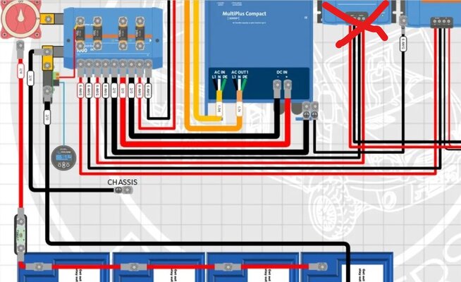
I've changed my build from a basic bus bar configuration to using a Victron DC in with the modification that allows it to act as a bus bar/fuse holder aka a dumb lynx distributor.

I am once again lost about whether or not I should run a 2/0 chassis ground at the bus bar since I'm using 2/0 wiring for all the battery/multiplus connections.

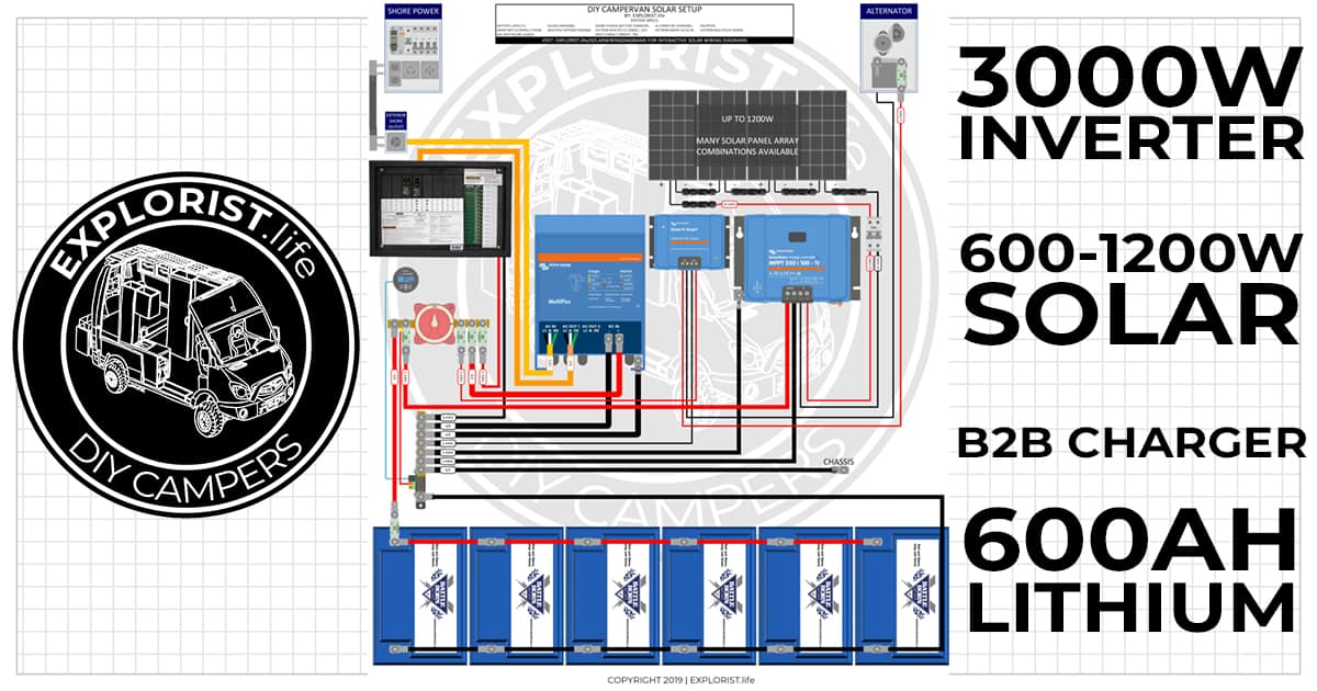
the red X on the diagram is a orion dc/dc which I won't be using since this is a TT RV I'm doing the install on. module to the right of it is the MPPT.

source link for wiring diagram:
source link for modifying a Victron DC in to a dumb Lynx distributor

Wiring diagram for solar.jpg

Looks like someone had a similar question on the Victron community page, and didn't get any answers.
 
I was confused, then less confused, and now more confused again.

I've changed my build from a basic bus bar configuration to using a Victron DC in with the modification that allows it to act as a bus bar/fuse holder aka a dumb lynx distributor.

I am once again lost about whether or not I should run a 2/0 chassis ground at the bus bar since I'm using 2/0 wiring for all the battery/multiplus connections.

the red X on the diagram is a orion dc/dc which I won't be using since this is a TT RV I'm doing the install on. module to the right of it is the MPPT.

source link for wiring diagram:
source link for modifying a Victron DC in to a dumb Lynx distributor

View attachment 158251

Looks like someone had a similar question on the Victron community page, and didn't get any answers.
the victron diagram is mostly correct, my exception to this would be the battery disconnect that should be on the negative side of the battery, but that's my personal opinion. now, for the chassis tap, again, in my opinion, there should be no requirement to use such a heavy cable such as 2/0 on a chassis ground, UNLESS, some idiot has used the chassis for a current return path, this is not good practice in my opinion for a non motorized travel trailer with questionable chassis design. best practice would be to have an individual return path for every device back to the load center and then a single return to the battery. IF your particular TT has a chassis return, then you can use the shunt to measure it, to do this, disconnect the negative at the distribution bus bar and run everything 12V on your system and see what the shunt reports.. I would be surprised to see a current of more than a few amps, in which case you could use something like 10 AWG and have done with it.. IF on the other hand you run a slide out and you see a 30 amp draw then you have a chassis return and will need to fit a heavier cable.
 
the victron diagram is mostly correct, my exception to this would be the battery disconnect that should be on the negative side of the battery, but that's my personal opinion. now, for the chassis tap, again, in my opinion, there should be no requirement to use such a heavy cable such as 2/0 on a chassis ground, UNLESS, some idiot has used the chassis for a current return path, this is not good practice in my opinion for a non motorized travel trailer with questionable chassis design. best practice would be to have an individual return path for every device back to the load center and then a single return to the battery. IF your particular TT has a chassis return, then you can use the shunt to measure it, to do this, disconnect the negative at the distribution bus bar and run everything 12V on your system and see what the shunt reports.. I would be surprised to see a current of more than a few amps, in which case you could use something like 10 AWG and have done with it.. IF on the other hand you run a slide out and you see a 30 amp draw then you have a chassis return and will need to fit a heavier cable.

I ended up getting 2/0 welding cable and probably enough to do a chassis ground provided I can actually find a place to access the chassis from inside of the cargo passthrough.

Unfortunately I can't do the measurement technique you're talking about as the LA house battery on the trailer is shot.

I suppose I could connect the LifePo battery to the current battery cables when it shows up and check that way. But the batter is on the tongue and the bus bar is at the power distribution panel 15' away inside.

Would there be a way to use a multimeter to test for the chassis return? Provided I have one person to look at the meter and one person to run some DC loads?
connect the battery positive to the distribution bussbar and use the multimeter in current mode to measure the current from the battery negative to the chassis, have someone turn on loads in sequence, measure the current ( if any ... )
 
Don't do it this way
Thor did their ground in a poor location under the RV where it gets wet every rain so it needs cleaning and regular maintenance.
 

Latest posts

Members online

Forum statistics

Threads
131,964
Posts
1,388,314
Members
137,717
Latest member
aquaticvegetation
Back
Top Bottom