Yet another solenoid bites the dust <from June 2008>

The friendliest place on the web for anyone with an RV or an interest in RVing!
If you have answers, please help by responding to the unanswered posts.

John Canfield

Site Team
Joined
Aug 8, 2006
Posts
14,121
Location
Texas Hill Country
As time goes by, I will be bringing over some of the interesting threads I started in another forum in an attempt to add to our body of knowledge here.  This particular thread, originated  early summer, had over 6,000 views before it died. It will take a few days to recreate the essential knowledge of the original 11 page thread, so be patient while this unfolds.  If you have anything to contribute to the topic, please fire away!
~~~~~~~~~~~~~~~~~~~~~~~~~~~~~~~~~~~~~~~~~~~~~~~~~~~~~~~~~~
The "seed" post:

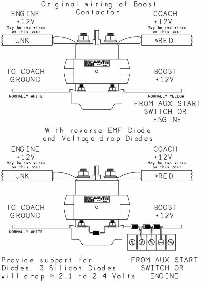
We have now had our second or third failure of the battery bank bridging solenoid. This is the solenoid that energizes when you are running the engine to charge both battery banks, and energizes when you operate the "Battery Boost" switch.

I don't know why we have had so many failures, but I am about ready to yank it out and install a diode isolator (no moving parts!)

The disadvantage of the isolator is no more battery boost switch (unless I add that back in) and the diodes have a 1.2 volt voltage across them which will be manifested as heat (if 50 amps are passing through one diode to charge a bank, you have 60 watts that need to be dissipated.)

 
John, I had this same problem earlier this year on my older '97 gas Bounder.  In the process of diagnosing and repairing the subject solenoid I assembled a set of procedures and created schematic diagrams for the various iterations of the "Custom RV Products" BCC. 

Documentation on the newer Intellitec version of the BCC is much easier to come by on the web.

I'll be interested in reading your discussion material.

Lou
 
Gary,

AFAIK, it is not used.  Converters and/or inverters are made by Dimensions (now owned by Sensata Tech), or Xantrex.  Xantrex is not currently used.  There is no charge control other than the alternator regulator when under engine power - not the best situation for me since my house battery bank is AGM and the chassis batteries are flooded cell.
 
John, where is this isolation (bridge) solenoid located if not in a Battery control Center box?
 
Lou - in our coach it's located in the electrical compartment with the power cord, inverter, cable/phone/portable sat dish hookups.  Driver's side just forward of the rear tires.  There is a metal box with two solenoids: one is to disconnect the house bank for storage (or whatever) and the other solenoid bridges the house/chassis banks together automatically when the engine is running, or it can operated on demand without the engine running - Winnie calls it a "Battery Boost" switch.
 
Okay John,  apparently Winni doesn't use either the Intellitec or the RV Custom Products BCC to perform that function. 

On many Coaches the boxes mentioned above house the battery disconnect solenoids, the bridge solenoid, the "BIRD" function (bridge solenoid control circuitry) and fuses for various chassis 12 volt circuits added by the Coach manufacturer.  Namely, fog lights, generator, aux start (battery boost), lp detector, etc....
 
Mark (Mr Transistor on another forum) gave me permission to post his excellent schematic of the diode 'fix' to lower the coil voltage which extends the solenoid life and the proper diode orientation on the coil terminals to prevent back EMF when the coil operates.  I quote from a post of his:

"I would definitely go with the contactor with silvered contacts. The copper contacts just don't provide the consistently low resistance required in a bridging application. Unless you are prepared to open the device to clean the contacts when they fail to provide this low resistance.

As far as the heat in the coil, a 2 or 2.5 ohm resistor of 15 or 20 watts will work just fine. If you chose to use diodes, 3 silicon diodes would provide about 1.8 to 2.4 volts drop depending on the device. Counter EMF (back voltage when the device is turned off) could be quite high given the iron core and number of turns of wire in the contactor. An 800 or 1000 volt rating for the diodes should be more than enough.

You could use much lower voltage ratings for the diodes if one more diode is added across the coil as a counter EMF shunt. i.e. Install the diode with the anode to the ground lead and the cathode to the +12 volt side right at the contactor. Then when voltage is removed, the counter voltage briefly forward biases this diode and shunts the current preventing the high potential that can arc contacts and destroy diodes.

Use diodes with about a 2 Amp. continuous rating and all should be well. The diodes that Jeff proposes should work just fine. The 50 PIV devices probably won't unless the counter EMF diode is also added."
 

Attachments

  • trombear.jpg
    trombear.jpg
    68.8 KB · Views: 77
Thanks John, looks like a good fix.

I have not had a continuous duty solenoid fail from coil heat as yet.

I have had failures from the copper contactor surfaces inside the solenoid (both tacking and high resistance) though.

I guess the silvered contacts would be a great improvement. I would think these would be commonly used in starter solenoid applications.  I'll have to research the cost.
 
Lou - I'll be posting some replacement candidates a little later.  Silver is the way to go, actually the best is silver contacts with a 14-15 volt rated coil.

A contributing factor for failures is probably the heat generated in the compartment and the solenoid being enclosed in a relatively small area.
 
Just doing a few quick google searches seems to indicate that silver contacts about doubles the price of the average solenoid.  Most are in the $30 to $60 range anyway, so not bad at all.

Like I stated in my first post in this thread, I repaired my solenoid about a month ago.  I'll see how long it lasts.

If you don't mind prying them apart, they are simple to repair.

I recall "burnishing" many relay contacts back in my Navy days of "wooden ships and iron men".  I still have a burnishing blade issued with my first IBM tool kit in 1959.
 
You could also install a diode ACROSS the terminals to let your converter supply a maintenance charge to the chassis battery.

Normally it will only carry a small amount of current, but you need something that can handle the full output of the converter on occasion.  The easiest solution would be a diode isolator like you'd use in place of the relay, but connected differently.

Connect the Alternator input on the isolator to the House 12v terminal on the relay, and either (or both) outputs to the Chassis 12v terminal.

When the relay is off, the isolator will let current flow from the House circuits to the Chassis circuit, but not in the other direction.   There will be a 1.2 volt drop due to the diode, but it should be enough to keep the chassis battery up.
 
I still like the solenoid method of isolation and bridging.  Especially when it's supported with the necessary circuitry to sense excess charge voltage available to either the coach or chassis batteries and close the path to provide charge in the other direction.  What could be better than that?

Makes me wonder why I keep hearing about all these high dollar coaches that don't have chassis battery charging from the coach system when it's standard on my old Bounder ???
 
Lou Schneider said:
You could also install a diode ACROSS the terminals to let your converter supply a maintenance charge to the chassis battery.

Yes - you certainly could do that for a trickle to the other battery bank.  Not sure how well that would work if the house bank was in float mode at 13.2-13.6 volts and with a silicon diode dropping about 0.65 V -  you could only be supplying 12.55 - 12.95 volts.  That idea might be more feasible with a Schottky diode since they only drop about 0.2 volts, but I don't know what kind of power they can handle.  It's probably better to just install a purpose-built product to charge the other bank.

I tried to disassemble my last failed solenoid (Winnie uses Trombetta) and it was not possible without resorting to drilling out rivets.  Took it partially apart and stopped and then I sent it to my contact at Winnebago since they collect failed parts for vendor analysis.
 
12.5 -12.9 volts is enough to keep the chassis battery from discharging - it's voltage will drop that far as soon as the surface charge is depleted, then the converter will keep it from discharging any further.

On second thought, I think I'd put a resistor in series with the diode - maybe an ohm or two.  It won't have any effect on low current charging, but will limit the current flow from the house batteries while cranking the engine.
 
I still have all my diodes in a box waiting for me to install them (Don't wanna be too quick about these things :) ). Might be a good Quartzsite project after having enough of the show..
 
Back
Top Bottom