Winnebago-Basement Air - Amps - Question?????

The friendliest place on the web for anyone with an RV or an interest in RVing!
If you have answers, please help by responding to the unanswered posts.

winnie32v

Well-known member
Joined
Mar 17, 2012
Posts
182
When I start up my Onan 5500 Generator and turn on my A/C, the amp reading on my Power Manager is 14.
The set temp is 65, the cabin temp is 85.
I was under the impression that I should expect BOTH compressors to kick in, creating a demand of around 20 - 24 amps.

Could someone explain to me what is going on here?

I'm wondering if I have a problem bringing the second compressor up.
The unit IS pushing cold air and the temp is slowly dropping.

Let me know if I'm missing something.
Thanks.


Edit by John:  changed message icon to Topic Solved
 
The second compressor should come on. Check your energy management for green lights on Rear AC Compressor and Rear AC Fan. If they are on the compressor and fan should come on. Check the breaker for the rear AC.
 
Also remember that there is a delay before the second compressor comes on. I think mine is about 15 to 20 seconds. There is a separate breaker for #2 compressor also. make sure its on. I turn off my #2 breaker when on 30 amp service.

Jerry
 
John Canfield said:
Yes, both compressors should pull ~21-24 amps and should be running.  Is this a new situation or something you just happened to notice?

Hummmmm,
I haven't had the unit that long to check this out, but I DO seem to remember that the unit did pull amps in the 20's earlier in the summer.
 
Wizard46 said:
Also remember that there is a delay before the second compressor comes on. I think mine is about 15 to 20 seconds. There is a separate breaker for #2 compressor also. make sure its on. I turn off my #2 breaker when on 30 amp service.

Jerry

Do you have any idea where this breaker would be located?
I wasn't aware that there were separate breakers for the two compressors.
Thanks.
 
winnie32v said:
Do you have any idea where this breaker would be located?
I wasn't aware that there were separate breakers for the two compressors.
Thanks.

Mine is in the main breaker panel under the foot of the bad, not sure on the Adventurer.

Jerry
 
When you run the generator I think the second compressor is supplied power by a second winding with a 20 amp breaker on the generator. I don't think that line is monitored by the EMS system. You might want to call Winnebago and check.
 
On my Adventurer the load center breakers are located just in side the door at the end of the kitchen cabinet.
 
I agree with others that you should be seeing about 24 amps with both compressors running. My Suncruiser, which is like an Adventurer, has a breaker panel in the kitchen cabinet under the sink. There are definitely two breakers - one for each compressor.
 
UPDATE....................

Here is what I did:

I found both AC breakers in my main panel (one was 30a, the other 20a), turned both all the way off, then back on again. Now I know they are set properly.

I plugged in the shore line to my garage outlet.
Then I turned on my Air Conditioner.  Amps went to 14a, then after about 5 seconds, I heard a 'sound' and amps went up to 20a.  I expect that the second compressor kicked in from the sound.

Air coming out of the vents was cold.
When the coach temp was 1 degree below the set temp, the AC automatically shut off.

So, I will conclude that both compressors are working, at least on shore power.

Now, what is going on with the Generator?  I only see an amp load of 14a with the AC on. 
At suggested, either there is a malfunction in one of the switches or the Load Center is not wired to pick the 2nd compressor load.

I will call Winnebago on Tuesday and try to get some insight from their Customer Svc. rep.

In the meantine.....any comments, suggestions or things to try from the Forum?

Thanks for all of the advice and comments, so far.
The saga will continue............
Regards,
Paul

 
Apparently you have 30 amp shore power and not the optional 50 amp.

Look at page 2 of your 110V wiring diagram - pop off the cover of your automatic transfer switch and make sure you have 110V on both sides of the generator output (CB1 & CB2.)  Be EXTREMELY careful when you are metering around the switch with live AC voltage!!

I'm thinking you either have a missing (CB2 of the gen output) leg from the gen set or a bad contact on the transfer switch.
 
John Canfield said:
Apparently you have 30 amp shore power and not the optional 50 amp.

Look at page 2 of your 110V wiring diagram - pop off the cover of your automatic transfer switch and make sure you have 110V on both sides of the generator output (CB1 & CB2.)  Be EXTREMELY careful when you are metering around the switch with live AC voltage!!

I'm thinking you either have a missing (CB2 of the gen output) leg from the gen set or a bad contact on the transfer switch.


John, Here's your update:
I checked CB1 & CB2 and got 120v on both with the Gen running.

I also did this: 
While the generator was running, I turned on the AC.  After start-up, it was pulling 14a.  I went to the breaker box and turned off the #2 AC, did not notice any change in compressor sound or amp change (didn't expect to).

I shut off the generator and plugged into shore power - 30a, as you suspected.
I turned on the AC.  It settled to 14a and then about 20 sec later, it went to 24a.  I expect the compressor #2 kicked in ... sound change was noticeable.

Next, I went to the breaker box and turned off the AC Breaker, 20a (Compressor #2).
Immediately the sound changed and the amp load went back to 14a.
So, looks like the compressor #2 WAS running and I was able to shut it down by using the breaker.
Turned the breaker on and Compressor #2 kicked in (some shedding occurred due to the big amp draw.)

AT LEAST, I know the #2 compressor IS working and not a basket case!

So, I'm back to the Generator IS supplying power to the Automatic Transfer Switch, BUT Compressor #2 is not kicking in.

Must be another switch or relay that is not working somewhere down the line.

Any new advice?????
Thanks,
Paul
 
At the transfer switch (refer to the diagram of your transfer switch), meter for 120V on the "Panel" or right side of the diagram - "Hot 1 BLK" and "HOT 2 RED" should both read 120V.  If you have voltage there, then your transfer switch should be good and you can button that up and move on.

Next, take the cover off the breaker panel, the "LOAD CENTER" on the diagram and meter for 120V on the leftmost 30 amp breaker (that's your panel feed and you almost certainly have voltage there) and then on the leftmost 20 amp breaker - that is feeding one of the two compressors.

Air conditioning circuit #1 is fed from a 20 amp breaker from your load center and it looks like A/C circuit #2 is fed directly from the transfer switch and using a gen set circuit breaker for protection.
 
John Canfield said:
At the transfer switch (refer to the diagram of your transfer switch), meter for 120V on the "Panel" or right side of the diagram - "Hot 1 BLK" and "HOT 2 RED" should both read 120V.  If you have voltage there, then your transfer switch should be good and you can button that up and move on.

Next, take the cover off the breaker panel, the "LOAD CENTER" on the diagram and meter for 120V on the leftmost 30 amp breaker (that's your panel feed and you almost certainly have voltage there) and then on the leftmost 20 amp breaker - that is feeding one of the two compressors.

Air conditioning circuit #1 is fed from a 20 amp breaker from your load center and it looks like A/C circuit #2 is fed directly from the transfer switch and using a gen set circuit breaker for protection.

I am plowing through my pack of literature....I may be getting old, but I seem to remember that I read somewhere a description of the use of #2 compressor when on shore power and on generator .....One shed the #2 compressor for some reason and I think it may have been the gen??????

Oh well, I'll check out the other wires that you referenced tomorrow AND will look forward to my call to Winnebago Cust. Scv. on Tuesday.

Regards,
Paul
 
Did you make sure both breakers on the generator itself is set. There should be a 30 amp and a 20 amp breaker on the panel on the generator.
 
John Canfield said:
At the transfer switch (refer to the diagram of your transfer switch), meter for 120V on the "Panel" or right side of the diagram - "Hot 1 BLK" and "HOT 2 RED" should both read 120V.  If you have voltage there, then your transfer switch should be good and you can button that up and move on.
BOTH Hot #1 & Hot #2 read 120v when the gen is running.

Next, take the cover off the breaker panel, the "LOAD CENTER" on the diagram and meter for 120V on the leftmost 30 amp breaker (that's your panel feed and you almost certainly have voltage there) and then on the leftmost 20 amp breaker - that is feeding one of the two compressors.
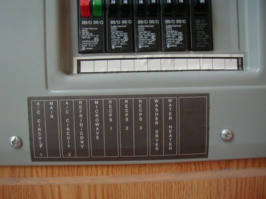
From Left to Right the 1st three breakers are:  Position #1 = 20a AC (#1 Compressor);  Position #2 = 30a Main;  Position #3 = 20a AC (#2 compressor):  ALL three read 120v with Gen running.


Air conditioning circuit #1 is fed from a 20 amp breaker from your load center and it looks like A/C circuit #2 is fed directly from the transfer switch and using a gen set circuit breaker for protection.
From what I see, Compressor #2 is fed from the 3rd 20a breaker (see above).

John,
Please let me know if anything else comes to mind. 
From what I've observed and after reviewing the wiring diagram that you sent to me, it is possible that this system is functioning as designed.
I'm looking forward to my call to Winnebago tomorrow.

Regards,
Paul
 
ME:  Air conditioning circuit #1 is fed from a 20 amp breaker from your load center and it looks like A/C circuit #2 is fed directly from the transfer switch and using a gen set circuit breaker for protection.

YOU: From what I see, Compressor #2 is fed from the 3rd 20a breaker (see above).

That's not correct.  Are you looking at the 30 Amp wiring diagram - there are two almost identical diagrams, yours will say in small print near the bottom right: "12D ELECTRICAL SYSTEM 30 AMP"

Now I'm wondering about the accuracy of all of your measurements.
 
John Canfield said:
ME:  Air conditioning circuit #1 is fed from a 20 amp breaker from your load center and it looks like A/C circuit #2 is fed directly from the transfer switch and using a gen set circuit breaker for protection.

YOU: From what I see, Compressor #2 is fed from the 3rd 20a breaker (see above).

That's not correct.  Are you looking at the 30 Amp wiring diagram - there are two almost identical diagrams, yours will say in small print near the bottom right: "12D ELECTRICAL SYSTEM 30 AMP"

Now I'm wondering about the accuracy of all of your measurements.
Yes, I was using the 30a schematic, not the 50a.  I even marked then in the margin in Red.

All of the measurements that I took align perfectly with your requests AND with the schematic you sent.

The reason I made the Compressor #2 statement:
When I was hooked up to shore power, I turned on the AC.
The first compressor kicked in and the load was ~14a.  In about 20 sec, a second compressor kicked in and the load went to ~24a.
So, I expect that BOTH compressors were working at this time.
While the AC was still on, I went to the Main Breaker Box and turned off the 3rd (from the left) 20a breaker A/CX Circuit #2).
Immediately one of the compressors shut down and the load center read ~14a. I am calling this compressor #2.  If this is #2, then I concluded that the power had to go through this breaker to activate compressor #2.

John,
Maybe I'm missing something....please let me know, if so.
Possibly to clarify the correlation between the wiring schematic and my actual Breaker Box...I have attached a photo of my Main Box:  The breaker labels read from left to right, A/C Circuit #1, Main, A/C Circuit #2. I expect that A/C Circuit #2 is compressor #2.

Please advise.

Thanks,
Paul
 

Attachments

  • Main Breaker Box.JPG
    Main Breaker Box.JPG
    53.6 KB · Views: 32
Back
Top Bottom