78 Dodge Glendale Motorhome House Batteries Overcharging

The friendliest place on the web for anyone with an RV or an interest in RVing!
If you have answers, please help by responding to the unanswered posts.
The engine battery is about a year old, its a sealed unit also.


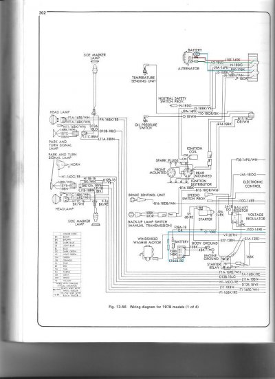
Alsight so I was going to try to test the voltage coming directly out of the alternator but is it really difficult to get the voltmeter probe in there cause there is no space so I wasn't able to do that. But I did find that there are two other wires that connect to the alternator a red a green one and they looked pretty corroded and the connectors were really loose. So I put new ends on them and fired it up crossing my fingers, but the same thing...

It seems that the red and green wire contol the voltage as it is the same color wires that come off the regulator, but I couldn't trace them cause they were in a big bundle of wires that I will have to unwrap another day.

I also traced the charging wire that comes off the back of the alternator to the battery isolator and it looked to be in good shape so I doubt that if I measured the voltage at the alternator output compared to at the isolator I would see any difference.

So I pulled out the alternator and I will take it to the parts store to get it tested tomorrow and post the results. Hopefully it is faultya nd then I can just get a replacement and everything will be good.


If you are using a diode isolator the voltage at the alternator should be 0.2 volt higher than at the battery.

However Diode Isolators often have 4 poles, Alt-Bat-1,Bat-2 and SENSE, now some alternators have built in voltage regulators (GM for example favors that design) Some have external regulators (I think Dodge favors that design) some have external SENSE and some don't (Sense is voltage sense by the way) some have only a single terminal, That's all, they are "Self Exciting" Ford has a few of those in their inventory I'm told (never seen one)

If the sense lead, should it exist, is not properly connected or if the small diode that feeds it is blown (It is the smaller of the 4 screws on the isolator) you will get over charging,  Just as you see.

Also, if you think it might be a regulator issue (Which by the way it is) you might wish to contact XANTREX.

They now make a regulator designed special for motor homes, I don't know much about it only happened to glance at it the other day while doing other research.  Supposed to give you a 3-stage type regulation. Sounds interesting
 
Hi John,

My isolator only has 3 screws, one for alt input and 2 output that's it no sense. The voltage drops about .4v when comparing the alt input to each of the outputs. The regulator is a separate unit that is mounted to the firewall above the engine, and it has two wires connecting to it a red and green one. The alternator has three wires coming off of it, one that carries the charge labelled BAT, goes directly to the alt input on the isolator, and a green and red wire. The green and red wire each connect to the alternator at a terminal called FLD, but they are both called FLD. Maybe they are mixed up? I don't think the green and red wires go directly to the regulator, I believe they go to some sort of a connection above the battery on the drivers side of the unit also mounted to the firewall. Now I don't know if they just connect there or if they go somewhere else and connect or what, I will have to take a closer look tomorrow once I find out if the alternator is good or not.
 
In a nutshell, the regulator supplies current to the Field terminals and that's how it regulates the alternator output voltage. Since your regulator is new and the alternator is new (rebuilt?), it seems likely the problem lies in the wiring between them. Either the regulator is not sensing the alternator voltage properly or too much voltage/current is being fed back to the alternator field terminals.  For example, a poor sense connection would likely lower the voltage the regulator sees from the alternator and cause it to boost the field voltage/current and therefore increase the alternator output voltage.

I've found THIS article to be helpful in  understanding what is going on in an alterantor. There are better written articles available, but they deal mostly with modern alternators with internal regulation and there isn't much a DIY person can do with those. You have an older external regulator type, so it is necessary to understand how the two components interact to trouble shoot them.
 
Roamer thanks for that article it helped clear up how the chargins system works.

I found these two articles. The first shows my exact setup under Mopar 1970 and up, and the second one shows identical shots of my regulator and alternator.

http://www.imperialclub.com/Repair/Electrical/charging.htm
http://www.440source.com/altparts.htm
 
Here is a link to the type of DC clamp ammeter I was talking about. 

http://www.hoytmeter.com/products/products_details.php?pro_id=821

 
Let me jump in here with my two cents. Lots of good suggestions have come before me.

First, re-wire that isolator completely using new wire and connectors, and get it the H--l away from the RADIATOR! Heat is its' worst enemy.

Second, a silicon diode will have a .6 volt drop between the input and output. Not .2, not .7; but .6 Anything other than that indicates a problem elsewhere. Yes, a germanium diode is different but we're not using them here.

Third, a very minor correction. The alternator output is controlled by applying a varying voltage (some use a varying width string of voltage pulses) to the armature, not the field, through the slip rings. The field carries the output power.

Fourth, if the slip rings are dirty or corroded, the armature is not getting the correct excitation voltage from the regulator, and an incorrect output voltage will occur. Have the alternator checked out.

Fifth, as was mentioned, some charging systems use a separate sense wire to measure the voltage AT THE BATTERY, to control the charging rate/voltage. If this wire doesn't read the true battery voltage, the charging rate/voltage will be incorrect. Make sure ALL connections are clean and tight. This means the large battery terminals and connectors too. Get a battery terminal cleaning brush and get those babies shiny and bright, then reconnect firmly. The difference you measured at the battery terminals could well indicate a bad connection.

Sixth, I wouldn't worry too much about the amperage at this time. It's the voltage that will determine the current flow to the batteries. Simply speaking, the higher the voltage, the more the current when flowing into a fixed resistance. There is a way to increase the range of an ordinary multimeter to read high currents, but I'll explain how that's done in a separate post.

Hope this helps :) 
 
Thanks Karl!

I am getting the alternator checked out today and I will also re-check the connections at the battery and clean them up if they are dirty. I think you may be dead on with the isolator dropping voltage .6v, it fluctuated when I measure it but it would have been right around there.

I'll post the alternator test results and try to get some actual numbers from them.
 
Re: The field windings on the alternator, There are only two ways to hook up two wires to the two terminals, The right way and the right way in this case (If you reverse them, it does not matter there is no ground reference and since it is an alternator the output polarity is decided via diodes not via field polarity as it is with a generator)

I have to agree with Karl, If the unit is outputting too much voltage this means the regulator is not sensing the voltage,

It has been a long, long, time since I worked on external regulator type alternators, but you need to measure the voltage at the battery or sense terminal on the regulator.  I am not sure which terminal that will be 

TO: carl... Regarding your slight correction (The controlled lines are the Armature, not the field)  True, but the terminals are labeled FIELD, likely because in days of old when Generators ruled,, That's what they were.  IF you wish you can call the Armature a "Rotating field" (Which I think is their official explanation for mis-labeling them) but hey..... You do have it right.  What is the other name for the fixed winding "Strator" I think? (Like I said, it's been a few..... Decades)
 
stator not strator, and you can lock that in. :) Somehow 0.7 volt sticks out for a drop across a silicon diode and 0.2 for germanium. It's been a long time since taking those EE courses so I won't lock that in.
 
Thanks for clarifying that the two FLD wires can be hooked up either way, so I can rule that out as being the cause.

If the alternator passes the test then it's time to start following wires to wee what is wrong... I noticed there are 3 wires connected at the positive battery terminal. One heavy one (starter) and two ther ones. Both of the other ones have connectors in line right near the battery so they can be disconnected? So maybe one of them is the wire for the battery sense?

I also have a Hayes manual for late 70's dodge vans (which is what the motorhome chassis is) that has wiring diagrams in it and I was trying to follow them but couldn't really find what I was looking for. I can scan the pages in when I get home from work later today and post them here so hopefully someone can help me figure out which wire to follow...
 
Unfortunately, the alternator test won't be conclusive with an externally regulated alternator. You will know if the alternator works (puts out amps), but will not be able to determine a "correct" voltage, because the output voltage is variable on this type of alternator. The regulator determines what voltage is "correct" at any instant.

The voltage regulator can sense the voltage at any point in the system - does not have to be at the battery terminals.  Basically it will manage voltage to some constant level at whatever point it is monitoring.  It could sense voltage right at the alternator or at any other convenient place. If it senses at the battery where the voltage is lower (because of the isolator voltage drop), it would react by increasing the alternator voltage until the battery voltage reaches the regulator's target voltage. That makes the voltage high on the input side of the isolator, but fine after it.

How many wires connect to the regulator? You mentioned two (red & green) but the photos I see online show 3 or more on some models. Also, the regulator itself undoubtedly needs a good solid ground. One of those wires will be the sense lead.

I would wire disconnect the existing wires that you can't follow through the bundle and run a new pair direct to the alternator (assuming you are confident that's where the red & green go). That will eliminate any problems there, at least for diagnostic purposes. If the new wires make no difference, you can go back to the old ones later.
 
RV Roamer said:
How many wires connect to the regulator? You mentioned two (red & green) but the photos I see online show 3 or more on some models. Also, the regulator itself undoubtedly needs a good solid ground. One of those wires will be the sense lead.

2 wires connect to the regulator, a red and green, also the same colors that connect to the FLD terminals on the alternator.

The diagram attached looks to be the exact setup of my system. Looks like the green wire should go directly from alternator to the regulator, same with the red but the red one also continues on to somewhere else. According to the wiring diagram in the Hayes manual the red wire does not go directly to the battery it goes elsewhere... So maybe the solution is to try connnecting the red wire from the alt to the voltage regulator and then directly to the battery or the input on the isolator? Input on the isolator would show the true voltage before the isolator drops it...

 
Alternator tested good. They hooked it up to a machine and then connected all the wires. The guy had to look up the year of the motorhoem to get the specs on it then hooked it up with a special harness. He said the machine tests its output at a variety of different voltages, so the machine actually has a built in regulator and some sort of a voltage and current sensor. So anyways it is good so looks liek it is a wiring issue.

Also with the ground for the regulator, I wire brushed both mouting holes so the case makes a good ground with the chassis as per the instructions with the regulator. So that can be ruled out also.

Looks like the wiring is the is somehow causing the issue. Do you think I should splice into the red wire and connect it directly to the battery to see if it makes a difference?
 
What the regulator does is to control the alternator such that the voltage COMING FROM THE IGN SWITCH is maintained at the desired voltage.  Check the voltage at the Field + terminal.  There could be a voltage drop in the wiring or ign switch.
Art
 
King said:
What the regulator does is to control the alternator such that the voltage COMING FROM THE IGN SWITCH is maintained at the desired voltage.  Check the voltage at the Field + terminal.  There could be a voltage drop in the wiring or ign switch.
Art

Thanks King. I think that is what the wiring diagram was trying to show me. So I should take a voltage reading of the red wire at the regulator or alternator? Then if it is lower I can trace that wire back to where it comes from which is probably the ignition switch. Maybe I should just get a new ignition switch they are only $20...
 
Wiring Diagrams attached

Green is the green wire from alt to reg
Red is red wire from alt to reg then to ign switch
Blue is alt output to battery and also to ign switch
 

Attachments

  • 1.JPG
    1.JPG
    126.6 KB · Views: 11
  • 2.JPG
    2.JPG
    137.4 KB · Views: 10
  • 3.JPG
    3.JPG
    135 KB · Views: 9
The wire going to the ignition switch has nothing to do with the regulation process. It's there to do one thing - shut off all current to the regulator so there is no drain on the battery when the ignition is off. Replacing the switch would be a waste of money and time. 
 
Karl said:
The wire going to the ignition switch has nothing to do with the regulation process. It's there to do one thing - shut off all current to the regulator so there is no drain on the battery when the ignition is off. Replacing the switch would be a waste of money and time. 

I see what you mean by looking at the diagram. I am going to test the voltage feeding into the regulator and the alternator via the red wire in the above diagram. If it is lower then I know the issue lies somewhere between the battery, ignition switch and the regulator.

I just need the weather to warm up, got about 6 inches of snow today too cold to work outside
 
Back
Top Bottom