7'x16' Enclosed Trailer Conversion - Electrical Panel & Breaker Design

The friendliest place on the web for anyone with an RV or an interest in RVing!
If you have answers, please help by responding to the unanswered posts.
Joined
Nov 15, 2023
Posts
21
Location
Massachusetts, USA
Hey, forum! I'm in the process of designing for and planning to convert a 7'x16' enclosed, cargo trailer into a living space I can tow. I'm a bit stumped by an element of the electrical system's design, and I'm hoping someone on the forum can shed some light or share their experience. I hope I chose the correct sub-thread to post this in! o_O

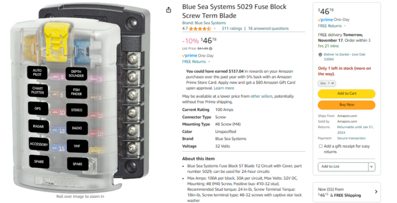
I'm planning to use a 120VAC/12VDC distribution center that I'll supply with a 30A service, and a combination of 15, 20 and 30A Square D, Homeline breakers. This is a link to the distribution center on Amazon. The bus bar for the breakers has room to accommodate 8, single-pole breakers in total, and I want to have plenty of outlets available in the trailer so I plan to use them all. My issue, though, is that the bus bar is actually two bus bars with 4 rails each, and my understanding is that you're expected to connect them with a 50A breaker. Without that 50A breaker, my understanding is that you're limited to only using one of the bus bars, half of the available breaker rails. I am going to use a 30A breaker because the F150 Powerboost's on-board generator is 30A, and the campgrounds I've visited all had 30A hook-ups.

I want to bridge those two bus bars so I can take advantage of all 8, available breaker rails, and I'm exploring different options. These are the design ideas I'm hoping folks can shed some light on. For the sake of simplicity, I am going to refer to the 8 rails along the two bus bars as 1A, 1B, 1C, 1D, 2A, 2B, 2C and 2D (from left to right).

Option 1: install one, 30A, double-pole breaker (link) across 1D and 2A. This double-pole breaker would connect both buses so I can use all 8 breaker rails. But, I understand this solution could result in a situation where 20 amps are being pulled from the left leg (rails 1A through 1C), and another 20 amps are being pulled from the right leg (rails 2A through 2C). In this situation, I understand the 30A breaker would not trip because each pole is afforded 30 amps and they're only pulling 20. My total current draw would be 40 amps on a 30 amp service, the breaker wouldn't trip, and this can result in melting wires and fires.

Option 2: install two 30A, single-pole, breaker (link) at 1D and 2A, and use a 10AWG jumper wire to connect them together. I'm thinking this will effectively bridge the two bus bar halves and will retain the intended functionality of the 30A breakers: if more than 30A is being pulled through either breaker, they should trip. The issue with this solution is that it adds the complication of having two "main" breakers that can be in different on/off (opened/closed) states, and I'd have to be very diligent about ensuring my system is properly de-energized when I work on it.

Looking forward to your thoughts and ideas! Thank you in advance for reading this novel-of-a-post and getting this far!
 
First a question on what you will do for the DC supply. This panel has no converter so what are you using for that? May be simpler to purchase a 120VAC 30A panel and a separate DC fuse panel than trying to make this one work.
 
Without that 50A breaker, my understanding is that you're limited to only using one of the bus bars, half of the available breaker rails. I am going to use a 30A breaker because the F150 Powerboost's on-board generator is 30A, and the campgrounds I've visited all had 30A hook-ups.
I read the product description like you did. It seems in the natural use of this thing in order to power both buses you need a 50 amp breaker and I am going to assume a 50 amp service.

Since you are trying to design this for a 30amp service I would continue looking for a 30amp box with the number of breakers you need.

There may be a way to parallel the buses with a 30amp service but it's clear the maker wants you to use a 50amp breaker so anything you do will be a bodge.

I reckon it's a bit misleading to have 8 breakers and in the fine print you can only use 4 on a 30amp.
 
You would be better off getting an RV power center such as made by WFCO. It will include both AC and DC including a converter for DC power. Even with many outlets you don't need many breakers. For my conversion I have 2; one for standard outlets and one for GFCI in the bath and kitchen areas.
 
As an alternative to my last post I agree with Ex-Calif. Get a load center for AC and a fuse block for DC.
It is raining here now but later I will take a picture of my setup and post it.
 
First a question on what you will do for the DC supply. This panel has no converter so what are you using for that? May be simpler to purchase a 120VAC 30A panel and a separate DC fuse panel than trying to make this one work.
I'm purchasing a 100W, 120VAC to 12VDC transformer that will provide the 12VDC to the panel. All of my lights and USB chargers, of which I will want plenty, will be powered from the 12VDC bus.
 
I read the product description like you did. It seems in the natural use of this thing in order to power both buses you need a 50 amp breaker and I am going to assume a 50 amp service.

Since you are trying to design this for a 30amp service I would continue looking for a 30amp box with the number of breakers you need.

There may be a way to parallel the buses with a 30amp service but it's clear the maker wants you to use a 50amp breaker so anything you do will be a bodge.

I reckon it's a bit misleading to have 8 breakers and in the fine print you can only use 4 on a 30amp.
Appreciate the reply! I'm an engineer by birth and by trade, so I want to make this thing work with my whole heart! But, you may be right...
 
You would be better off getting an RV power center such as made by WFCO. It will include both AC and DC including a converter for DC power. Even with many outlets you don't need many breakers. For my conversion I have 2; one for standard outlets and one for GFCI in the bath and kitchen areas.
Thanks for the reply! I understand what you mean regarding the number of breakers I'd reasonably need. I recognize, though, that there's a difference between what I would need and what I want to do with this project I am designing and executing all by myself, and I admit I will over-engineer this mofo. I'm very, very content with that, but your input is received!
 
Appreciate the reply! I'm an engineer by birth and by trade, so I want to make this thing work with my whole heart! But, you may be right...
40 year aero engineer... I too love to make things work.

But I am at the age where reinventing the wheel isn't as much fun (or time effective) as it used to be.

BTW - My 32 foot class a (30amp) only had a 6 breaker panel. Only 5 were used until I added electric hot stick for hot water. Point is 8 breakers may be overkill for a trailer.

For DC panels (even though they are for boats) I love Blue-Seas stuff. Really well made and plenty of capacities.

1700150976300.png
 
You have chosen the wrong type of distribution center. What you picked is a 240V main lug panel, but what you need is a 30A/120v subpanel. The distribution panel in an RV is always considered to be a subpanel of the shore power source panel, and must follow the NEC rules for subpanels. A 120v subpanel will have a single bus bar.

The number of outlets is not limited by the number of breaker slots - multiple outlets are daisy chained on a single branch circuit. The limitation is amperage, not slots. As a practical matter, it's hard to employ more than 3-4 branch circuit breakers on a 30A/120v supply.

You will also need a 12vdc distribution panel and a 12v converter/charger, so the easiest and most efficient space method is to get a combined 30A/12v power center designed for RV use, e.g. one from WFCO, Progressive Dynamics, Furion or other supplier. Here's an example from PD:
Couple of things:
1 - thank you for the thorough response and the time you took to write it!
2 - hoping you can help clarify your comment regarding what constitutes a "shore power source panel," a subpanel and NEC compliance. I'm considering using this WFCO, 30A Distribution Center after the feedback I've received so far. My plan is to land the hot of my shore power into a "master" fuse block, then to a 3-way switch (because I also want to be able to use my Jackery as the power source for the trailer when shore power isn't available), then from that 3-way switch's output to the distribution center's main breaker. The neutral and ground from the shore power input (and from the cable used to tie in the Jackery) will land on the distribution center's respective bus bars. In this way, I don't understand that I have a "shore power source panel" in my design. Is my design idea flawed/non-compliant?
3 - as I said in a reply above, I'm cognizant of what's practical versus what's possible. I'm most likely going to lean towards what's possible even if it costs me more in money and time so long as it's not strictly unsafe or "malpractice." I will use the maximum number of breakers I can and have the fewest daisy-chained circuits as possible.
 
You will be plugging the RV's power cord into a receptacle at an RV site or your driveway or wherever. That outlet is served by a main panel, so any panel in your RV is subsidiary to it, i.e. a subpanel. There are some differences in how a subpanel is wired, primarily in how the grounding is done. The key difference is that a subpanel ground is never "bonded" to the neutral.

Since you will only be connecting to RV 30A, which is a 120v supply, you need a subpanel with a single bus. That WFCO 8735 cited in your most recent post will work nicely. The original Arterra 8930/50 complicated things with the 50A/240v bus.

I re-read your original post and realized I misunderstood your proposed panel use, but it still seems a poor choice because of the 240v dual buses. However, you can overcome that by using a 30A/240v main breaker and using a jumper wire to feed both halves from the same 30A/120v source (your option #1). An electrical inspector would probably balk at that, but it functions just fine except for the loss of the 30A trip.

You can feed the power center from a transfer switch, whether automatic or a manual double pole- double throw switch. That lets you easily select shore power or inverter as the source while assuring that the two can never be active at the same time.

I think we are both on the same page now.
Thanks for the clarity! Makes sense that the panel at the campground site, or the on-board generator in the F150 truck bed, would be the "main panel."

The Jackery will only be connected to the switch when I want to use it as the power source, and that will exclusively be when my shore power is disconnected, so I don't think I need the safety of the ATS in this first phase's design. There will never be a situation where both power sources are simultaneously connected, so I'll stick with the 3-way DPDT switch. Second phase (years from now) of my design will include a solar system, so it may make sense to use an ATS then.
 
The OP appears to not be familiar with RV electrical systems, and is trying to re-invent the wheel.

You might do well to review The 12volt Side of Life (Part 1). and The 12 volt Side of Life (Part 2).

You NEED a battery, and the best way to keep it PROPERLY charged is NOT a simple transformer, but rather a multistage power converter designed for RV use. Either stand alone. or built into the power center.

Note: the converter situation, among other things, will change if you intend to install solar panels and lithium batteries.

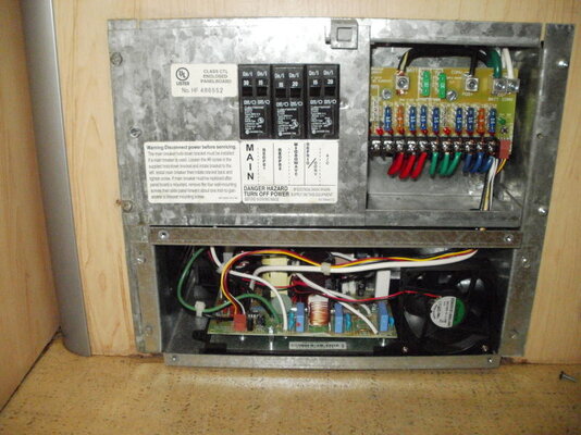
My personal preference is a Parallax Power Center with a Progressive Dynamics 46xx power converter installed in it. These power centers were extremely popular for many years in RV's until cheaper plastic ones took over, but you can find them in RV salvage yards, and stick a new converter (which comes with a new 12v fuse panel) in it. New buss bars with stabs and other small replacement parts are readily available, as the panels are still manufactured, but are $500 or so new. Any Winnebago up thru the 2010's with 30 amp will have this panel, and many others will also. The panel is ALL STEEL and that is why I prefer it.

The Parallax panel has a louvered cover (lower part) that screws on with a hinge top for access to fuses and breakers. I have owned three RV's and two of them have had the Parallax panels.

Charles
 

Attachments

  • Parallax panel with progressive converter.jpg
    Parallax panel with progressive converter.jpg
    96.1 KB · Views: 3
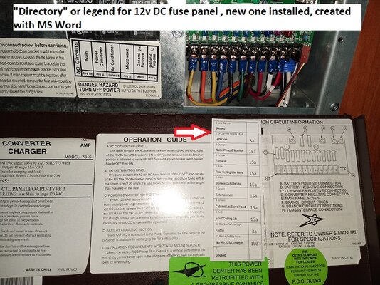
  • Ferrule inst dc fuse panel directory.jpg
    Ferrule inst dc fuse panel directory.jpg
    396.1 KB · Views: 3
The OP appears to not be familiar with RV electrical systems, and is trying to re-invent the wheel.

You might do well to review The 12volt Side of Life (Part 1). and The 12 volt Side of Life (Part 2).

You NEED a battery, and the best way to keep it PROPERLY charged is NOT a simple transformer, but rather a multistage power converter designed for RV use. Either stand alone. or built into the power center.

Note: the converter situation, among other things, will change if you intend to install solar panels and lithium batteries.

My personal preference is a Parallax Power Center with a Progressive Dynamics 46xx power converter installed in it. These power centers were extremely popular for many years in RV's until cheaper plastic ones took over, but you can find them in RV salvage yards, and stick a new converter (which comes with a new 12v fuse panel) in it. New buss bars with stabs and other small replacement parts are readily available, as the panels are still manufactured, but are $500 or so new. Any Winnebago up thru the 2010's with 30 amp will have this panel, and many others will also. The panel is ALL STEEL and that is why I prefer it.

The Parallax panel has a louvered cover (lower part) that screws on with a hinge top for access to fuses and breakers. I have owned three RV's and two of them have had the Parallax panels.

Charles
I appreciate the response, and suggest you consider whether you have an adequate understanding of the OP's (my) goals and objectives before suggesting what I am and am not familiar with.

Do you know that I don't already have a battery?
Do you know how much contiguous amount of time I intend to spend in the converted trailer at any point during the next 3 years? Or how that might change in years 4-6?
Do you know what appliances, or other electrical devices, might be connected to the electrical system?
Do you know that my personal goals and objectives aren't precisely re-inventing the wheel and not purchasing out-of-box, turnkey solutions?
 
So there are nuances to what you are designing. It might be a good idea at some point to draw a schematic.

As I understand it you want both 12VAC power and 12V power. If you aren't intending to have a battery then I guess you don't need a charger but that means you have to run the generator at all times or be plugged into shore power to get lights on?

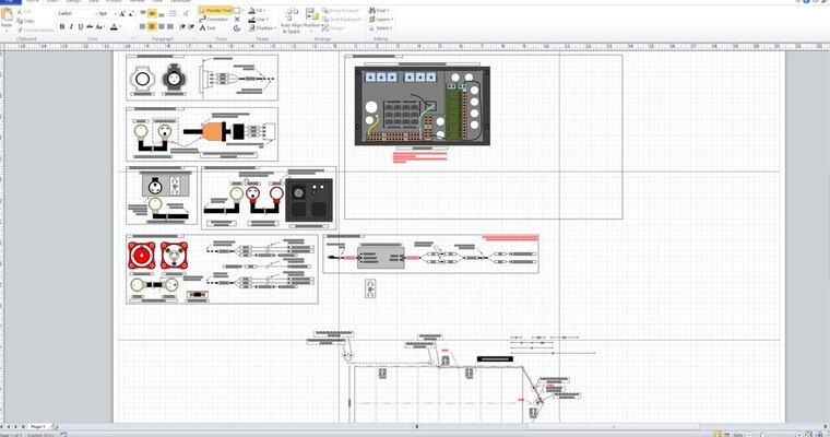
Drawing schematics/wiring diagrams/elevations is exactly what led to my joining this forum to seek guidance ;) It's far from finished, but I got to the point in my electrical distribution elevation where I realized I didn't know how to bridge the two buses, and thought it best to do some research before proceeding. I did my best not to give too much information about my plans for the trailer because I wanted people to focus on my specific question and issue, but maybe that was an unfair expectation. Happy to share more about my plans!

There are two phases to my plans through 2027/28. I plan to buy a new truck next year and a new trailer in the beginning of 2025. Through 2025, I want to be able to take road trips to family or places in the US with my now-girlfriend (who I expect to be my then-wife). She's skeptical about the whole "live out of a converted trailer for a week" dream, so I know converting her will be an uphill battle. Because I want to relocate to AK in 2027/28, and want to incrementally bring some of our belongings to AK (to be kept in storage/at a friend's spot until we permanently relocate), I need to be able to use the trailer as a traditional cargo trailer until we're there and settled. Thus, my two phases.

Phase 1: The things we'd need to comfortably boondock by a lake in Maine or something. The cute stuff while I'm trying to convince her to spend some time outdoors with me, but nothing that I can't pull out of the trailer if/when I need to haul stuff. In this phase, my power sources will be the F150 Powerboost's on-board, 7.2kW generator (30A) or my 2kW Jackery (portable solar generator & battery). Because every AK campground I've visited also had 30A services, I'm positioning the shore power inlet centrally on the trailer so I can connect it to a campground's panel in the future or the truck's generator, in the truck bed, without exceeding 30ft on 10AWG cable (avoiding excessive voltage drop). I also want to be able to power the trailer from one of my Jackery's 120VAC, 15A outlets if/when i'm going to be in it for a little while, but not so long that I need to run the truck's generator and consume gas. But, because I know I need to make things as straight-forward as possible for my now-girlfriend while she's trying something new with me, I don't want her to have to disconnect and reconnect a bunch of devices to be comfortable when we're running off the Jackery. That's why, instead of using the available AC & DC outlets on the face of the Jackery, I'm choosing to wire a single, 12 AWG extension cord into my shore power's 3-way, master switch's second input, terminate it onto a 15A breaker, and leave it neatly coiled on my electrical wall. Swapping from shore power to Jackery power should be: turn the master switch to the second position, plug the extension cord into the Jackery's outlet, make sure the 15A breaker is switched on, and turn the Jackery on. A couple of steps, yes, but fewer steps and faster than running extension cords from the Jackery to the outlets around the trailer and reconnecting devices to different ports. All of the same lights, AC outlets and DC, USB charging ports around the trailer will work the same whether we're on shore power or Jackery power (just with half the available amps).

For this phase of the trailer, these are the types of projects I'm planning/devices I expect to have with me: insulated and finished walls, ceiling and flore, ceiling fan, side-wall window, lights, portable diesel heater, battery-powered, portable fridge/freezer, inflatable mattress and electric blankets. Starlink for internet. Two, 7-gallon water containers and a battery-powered shower head.

Phase 2: when my then-wife and I are settled, and our family planning is... planned, I'll be able to do a more traditional, "full" conversion with solar, battery bank, on-demand water heater, plumbing, toilet and stuff like that. There are too many uncontrollable variables between today and phase 2, so I'm not budgeting or planning for it, yet. I do want to pull wires for things I can anticipate, such as an outdoor-rated outlet, to minimize how many of my walls i'll have to take down in Phase 2. But, for now, I'm content with my plans being atypical, unusual, or over-engineered as long as they're safe.

This has become the absolute novel of a post I was trying to avoid typing to begin with :censored: I hope this additional context answers your question and clarifies why I'm going down the path I'm traveling.

Schematics XD.jpg
 
Swapping from shore power to Jackery power should be: turn the master switch to the second position, plug the extension cord into the Jackery's outlet, make sure the 15A breaker is switched on, and turn the Jackery on.
OK - Here's a thought - On early coaches (like mine) there is no switch between shore and generator. The A/C electric panel has a 15 foot cord with a 30 amp male RV plug on it. The generator simply has a female box outlet. When using shore power the cord is plugged into the shore receptacle. When generator is used the A/C plug is simply plugged into the generator female feed box.

I am sure all of us will still recommend installing at least 2 batteries and a traditional power converter/charger - It won't be wasted especially when you get to phase 2.

In addition a 400W or so inverter is hooked up to the batteries.

This way for your GF - She knows that when she switches a light switch (12V DC) the light comes on. If you are not plugged into shore or generator she still has a 400W A/C outlet she can plug her laptop, charger or other light load even if the generator is not running or you are not plugged into shore power.I even run my tv and wifi off the inverter and battery when I need to.
 
Rick and Sharon of the YouTube channel Gonagain travel the western US from their home in Montana using a SUV and a converted cargo trailer. The have a Playlists page that includes their cargo trailer build. They also do equipment reviews and just today posted a review of a Bluetti AC200L.

You may find some useful information in their videos.

Also, be aware that most if not all states require a trailer to have brakes (usually 1500 lbs and above, but it varies with the state) and part of this is an emergency break away system that will set... and HOLD the brakes for (if I recall correctly) 15 minutes. Which is one good reason for going ahead and setting up the trailer with some sort of battery. Many cargo and utility trailers use sealed lead acid batteries for this purpose, but you will do well to set up a larger one for other uses, which can be swapped later for bigger/better/different.

A modern power converter is mult-stage, having various voltage levels to bulk charge a lead acid battery, then drop to a lower level during normal use, and a even lower level to maintain and possibly desulfate the battery without cooking it. I leave my trailer plugged in 24/7 and the battery dates back to about 2018 and shows no signs of quitting. A transformer will simply cook batteries and not be useful with future lithium batteries either. Many new converters will multistage maintain lead acid and can be switched to lithium ion, making it a once and done investment.

The power panel I suggested (and most other similar panels) have 12 to 14 fuse/circuit locations for 12v DC circuits, more than enough for everything conceivable in a small cargo trailer. True RVs are regulated by the National Electric Code article 70-551, which establishes limits on the number of branch circuits and many other factors in an RV electrical system.

Charles
 
Back
Top Bottom