rsalhus
Well-known member
- Joined
- Jul 20, 2006
- Posts
- 1,335
I thought about installing a baseplate myself to our new 2007 Saturn Ion after reading Tom Jones' illustrated article entitled "Installation of a Roadmaster Blackhawk heavy duty tow bar and base plate" in the RV Forum Library. Tom says that such a project is "definitely within the capabilities of the average do-it-yourselfer". Well, installing a tow bar is something even I can handle by myself, but tearing the front end off a car to install a baseplate? Read the following and take a look at the pictures below and judge for yourself.
I started off on this project by downloading the Installation Instructions from the Blue Ox website designed especially for our car (BX3325). The instructions had lots of pictures but the quality of the pictures left a lot to be desired. And the pictures that came with the baseplate were even worse (black and white vs color). I could tell right away that I would be in big trouble if I had to rely on these pictures to get the baseplate installed correctly. Luckily for me, I found someone to help me that was skilled way beyond the average do-it-yourselfer. My thanks go out to Kevin Krumm of Somerset, WI, who made this project successful.
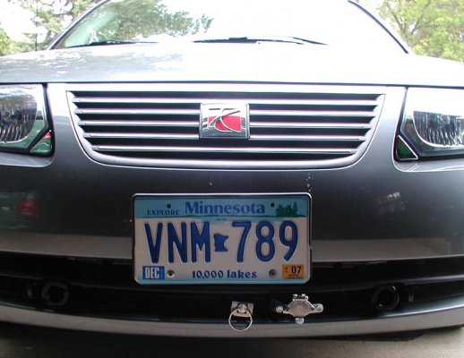
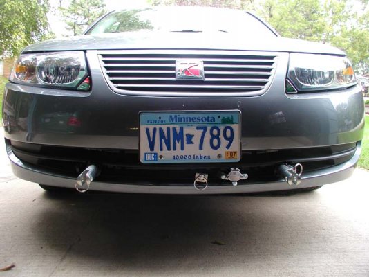
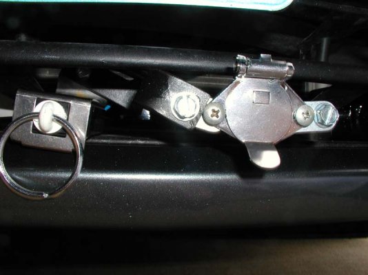
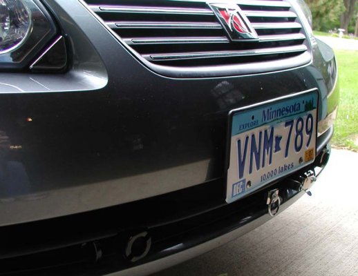
PICTURE 1 shows the end result of the baseplate installation. PICTURE 2 shows the baseplate with the tabs inserted. You can see that some trimming of the lower lip of the fascia rib had to be done on each side to make room for the two baseplate projections at the front of the Saturn. My helper (actually Kevin did most of the hard work, I was mostly the helper) also fabricated a piece of iron bar to one of the two holders for the electrical connector so that it would also hold the breakaway connector (for the Blue Ox Apollo Braking System) shown in the middle of the picture. You can see this in more detail in PICTURE 3.
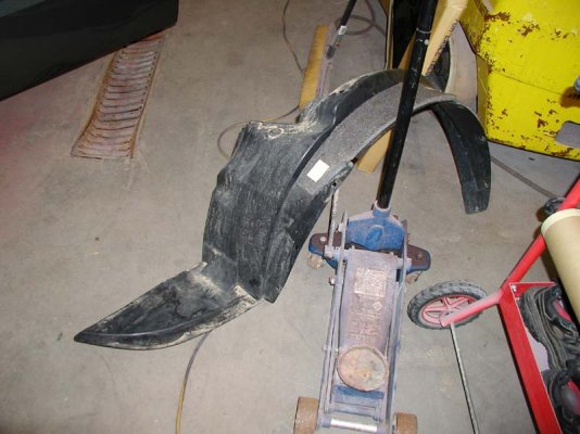
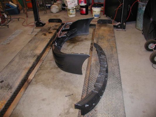
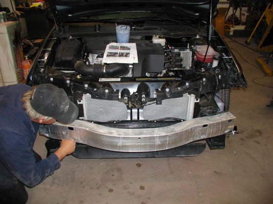
We started out by removing the plastic wheel well coverings from each side. PICTURE 4 shows the wheel well covering from the passenger side. PICTURE 5 shows the fascia (left) and the Styrofoam bumper (right) that came off next. PICTURE 6 shows the position of the metal bumper which came off next after removing the horn and the headlights and doing some trimming of the plastic air dam and a small section of the metal frame on both sides. This was difficult only because the installation instructions and pictures weren't very clear about how much to trim off.
Getting the baseplate in position required two people but wasn't too hard on the passenger side because an existing hole for the air baffle was used (by design) to hold the baseplate in the proper position. On the driver's side however, there was no such hole. We clamped the baseplate where we thought it should be and then measured each side from the floor to the bottom of the baseplate to be sure the baseplate was level. There were no instructions or pictures on how to do this. After clamping both sides of the baseplate to the frame, we used the baseplate as a template and drilled 3 holes through the frame on each side and one in front on each side.
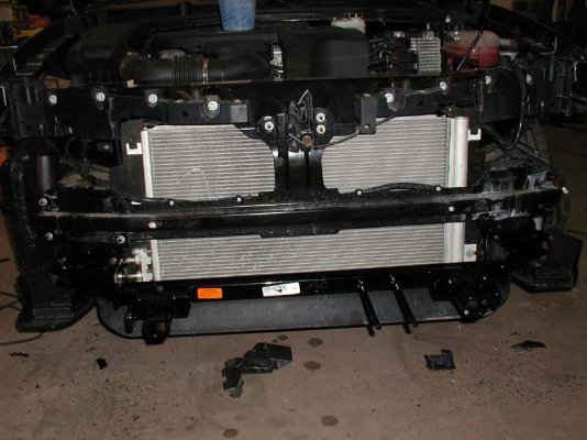
Next came the hard part - threading the mounting bolts to the nuts. The nuts were welded to long wires and had to be fished up a narrow, metal channel and handheld by the wire while attempting to thread it with the bolt. This is where we spent the most time. The wires had to be bent just right and to get the nut in the proper position was very difficult and the most time consuming part of the entire installation. We applied Loctite Red to the bolts and torqued them to the required PSI using a torque wrench. PICTURE 7 shows the baseplate after the mounting bolts were attached. The two round extension pipes pointing out the front from the baseplate are what hold the electrical wiring plug to the baseplate.
Wiring consisted mostly of running 6 wires through the firewall. Two wires were for the Blue Ox Apollo Braking System's breakaway system and the other four wires were for the Saturn's tail lights. We had to drill 1" holes in each tail light to insert an extra bulb as part of the Blue Ox Bulb and Socket Tail Light Wiring Kit (BX8869).
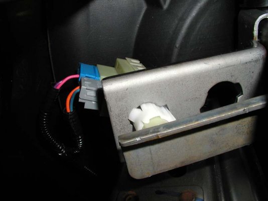
Another hard part was finding the wire to the Saturn's rear brake lights. Tapping this wire is needed by the Blue Ox Apollo Braking System to send an RF signal to a remote receiver in the motorhome to light a light when the toad's brakes are actually applied. I managed to squeeze my digital camera up under the dash to get a picture of this wire because it couldn't be seen any other way. PICTURE 8 shows this, it's the blue wire that has current when the Saturn's brakes are applied.
All in all, it took us 8 and 1/2 hours to get the baseplate installed and to do all of the wiring. This included a trip from Somerset to New Richmond to buy a hole saw that would work with plastic (we didn't want to chance breaking the tail light assembly with a wood hole saw). All I can say is that without my very talented helper, Kevin, I wouldn't have been able to come anywhere close to finishing this project by myself. Of course, I haven't had time to connect the Saturn to the motorhome yet to see if it all works.;D That will come later but I have a lot of confidence that everything will be just fine.
So, is this something you think is definitely within the capabilities of the average do-it-yourselfer? I don't think so, but you be the judge. :-\
I started off on this project by downloading the Installation Instructions from the Blue Ox website designed especially for our car (BX3325). The instructions had lots of pictures but the quality of the pictures left a lot to be desired. And the pictures that came with the baseplate were even worse (black and white vs color). I could tell right away that I would be in big trouble if I had to rely on these pictures to get the baseplate installed correctly. Luckily for me, I found someone to help me that was skilled way beyond the average do-it-yourselfer. My thanks go out to Kevin Krumm of Somerset, WI, who made this project successful.
PICTURE 1 shows the end result of the baseplate installation. PICTURE 2 shows the baseplate with the tabs inserted. You can see that some trimming of the lower lip of the fascia rib had to be done on each side to make room for the two baseplate projections at the front of the Saturn. My helper (actually Kevin did most of the hard work, I was mostly the helper) also fabricated a piece of iron bar to one of the two holders for the electrical connector so that it would also hold the breakaway connector (for the Blue Ox Apollo Braking System) shown in the middle of the picture. You can see this in more detail in PICTURE 3.
We started out by removing the plastic wheel well coverings from each side. PICTURE 4 shows the wheel well covering from the passenger side. PICTURE 5 shows the fascia (left) and the Styrofoam bumper (right) that came off next. PICTURE 6 shows the position of the metal bumper which came off next after removing the horn and the headlights and doing some trimming of the plastic air dam and a small section of the metal frame on both sides. This was difficult only because the installation instructions and pictures weren't very clear about how much to trim off.
Getting the baseplate in position required two people but wasn't too hard on the passenger side because an existing hole for the air baffle was used (by design) to hold the baseplate in the proper position. On the driver's side however, there was no such hole. We clamped the baseplate where we thought it should be and then measured each side from the floor to the bottom of the baseplate to be sure the baseplate was level. There were no instructions or pictures on how to do this. After clamping both sides of the baseplate to the frame, we used the baseplate as a template and drilled 3 holes through the frame on each side and one in front on each side.
Next came the hard part - threading the mounting bolts to the nuts. The nuts were welded to long wires and had to be fished up a narrow, metal channel and handheld by the wire while attempting to thread it with the bolt. This is where we spent the most time. The wires had to be bent just right and to get the nut in the proper position was very difficult and the most time consuming part of the entire installation. We applied Loctite Red to the bolts and torqued them to the required PSI using a torque wrench. PICTURE 7 shows the baseplate after the mounting bolts were attached. The two round extension pipes pointing out the front from the baseplate are what hold the electrical wiring plug to the baseplate.
Wiring consisted mostly of running 6 wires through the firewall. Two wires were for the Blue Ox Apollo Braking System's breakaway system and the other four wires were for the Saturn's tail lights. We had to drill 1" holes in each tail light to insert an extra bulb as part of the Blue Ox Bulb and Socket Tail Light Wiring Kit (BX8869).
Another hard part was finding the wire to the Saturn's rear brake lights. Tapping this wire is needed by the Blue Ox Apollo Braking System to send an RF signal to a remote receiver in the motorhome to light a light when the toad's brakes are actually applied. I managed to squeeze my digital camera up under the dash to get a picture of this wire because it couldn't be seen any other way. PICTURE 8 shows this, it's the blue wire that has current when the Saturn's brakes are applied.
All in all, it took us 8 and 1/2 hours to get the baseplate installed and to do all of the wiring. This included a trip from Somerset to New Richmond to buy a hole saw that would work with plastic (we didn't want to chance breaking the tail light assembly with a wood hole saw). All I can say is that without my very talented helper, Kevin, I wouldn't have been able to come anywhere close to finishing this project by myself. Of course, I haven't had time to connect the Saturn to the motorhome yet to see if it all works.;D That will come later but I have a lot of confidence that everything will be just fine.
So, is this something you think is definitely within the capabilities of the average do-it-yourselfer? I don't think so, but you be the judge. :-\
Attachments
-
 PICTURE 1.jpg81.6 KB · Views: 75
 -
 PICTURE 2.jpg87.9 KB · Views: 47
 -
 PICTURE 3.jpg67.1 KB · Views: 63
 -
 PICTURE 4.jpg79.9 KB · Views: 63
 -
 PICTURE 5.jpg81.8 KB · Views: 59
 -
 PICTURE 6.jpg83.9 KB · Views: 70
 -
 PICTURE 7.jpg83.2 KB · Views: 64
 -
 PICTURE 8.jpg53.5 KB · Views: 63
 -
 PICTURE 9.jpg77.4 KB · Views: 62
