Help, battery monitor

The friendliest place on the web for anyone with an RV or an interest in RVing!
If you have answers, please help by responding to the unanswered posts.

ROBIN52

Active member
Joined
Oct 17, 2020
Posts
39
Location
Chunchula, AL.
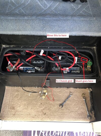
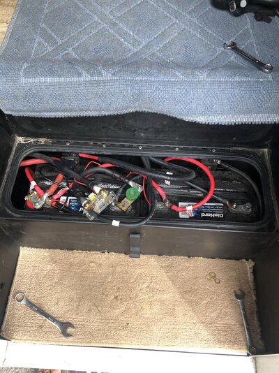
Good afternoon, have been reading and you tubing for a week and thought I had in my mind how to do. I installed a Renogy 2000 watt inverter and a second TS30 transfer switch and wired the converter to a fuse I installed in the transfer switch. All seems to work as it should. The problem came when I installed an Renogy 500A with shunt battery monitor. With the shore power disconnected and the inverter switch on, the monitor works as should and all the AC outlets work. When I turn off the inverter and plug into shore power the monitor just flashes, which the manual says it is not wired correctly. I will try and attach a pic of how I have it wired. I have the 2 negative cables going to the battery - on the shunt and my negative going to my inverter on the P - side of the shunt. Something is wrong and I can't figure it out.BATTERIES.jpeg
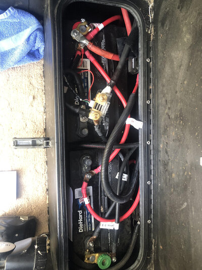
 
seems a wiring problem. carefully confirm your wiring design. focus on the battery monitor wiring which could be contingent on transfer switch position / inverter on or off.
 
It looks wrong to me. All of the returns (-) need to go through the shunt. From the picture, the bottom battery has one that does not (green disconnect). On the top battery, looks like there is another return that goes straight to the battery and not through the shunt.
 
It looks wrong to me. All of the returns (-) need to go through the shunt. From the picture, the bottom battery has one that does not (green disconnect). On the top battery, looks like there is another return that goes straight to the battery and not through the shunt.
Thanks for the reply. The top battery has a - cable that has a loop and goes to the shunt as well. The bottom battery, green disconnect - cable goes to the chassis. I thought I had read the chassis grd. to not go through the shunt. The two batteries have 2 - cables going to the shunt B-. So your saying the chassis grd. also need to need to go to the shunt?
 
The chassis ground must be the only ground connection through the shunt. Per the photo what is probably the inverter negative is going through the shunt but what looks like your chassis ground on the bottom battery does not. Time to step back and come up with a diagram to follow. Looks like you have enough there to do it right, it's just misconfigured.

Mark B.
Albuquerque, NM
Thanks, here is the original layout without the shunt attach. The battery on the left has my 2/0 cables going to the inverter. Can you tell me which cable I would use for the shunt B- and which cable I would use for the P- on the shunt? Thanks
 

Attachments

  • battery 2.jpeg
    battery 2.jpeg
    234.3 KB · Views: 9
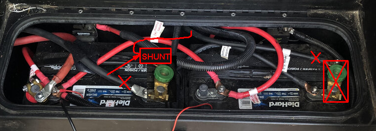
The way to wire it, is like this. Probably easier of you move the disconnect to the other battery so you can keep the existing cables.
battery 2.jpeg
 
The way to wire it, is like this. Probably easier of you move the disconnect to the other battery so you can keep the existing cables.
View attachment 163348
Thanks for the reply, this 70 year old still having a hard time wrapping my brain around this. let me see if I got this. You want me to move the inverter - wire over to the outgoing side at the green disconnect which goes to the chassis grd. The inverter wire is not long enough to reach over there. Or are you saying move the green disconnect over to the other battery and hook the - inverter wire to the which post of the shunt B- or P- ? and the chassis grd. to the other end of the shunt? I hate making this for you folks trying to help.
 
Move the disconnect to the other battery. Disconnect the inverter from the battery and connect it to the other side of the shunt.
 
Not ideal for high loads but you could move your switch to the other negative post, put your shunt there, then connect your inverter and chassis ground.

1680720638545.png

Mark B.
Albuquerque, NM
 
Let me ask a question, should the monitor be working while on shore power? If yes then I still have a problem. I have had it working correctly when off shore power and on inverter. And I can live with that. Thanks
 
Shunt should work on and off shore power. Go back and read the installations instructions again.

Describe what you are seeing now after making the changes Mark and I suggested and post another updated picture.
 
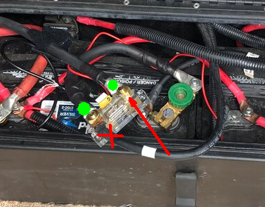
black cable with white reflective tape is on the wrong side of the shunt
That cable is the chassis grd. So your saying just move that one cable to the other side of the shunt? that would put the chassis grd. with the neg. cable going to the inverter. When the neg. cable going to the inverter is on the shunt it seems to only work when I turn on the inverter. Thanks
 
Per the pictures all you've done is reversed the direction of current through the shunt. The path from the battery negative to the shunt needs to be the only connection (the switch is OK in the path). I don't know how this monitor/shunt is intended to be connected in terms of indicating charge and discharge so it might be "backwards" but you'll figure that out in short order. If it's backwards you'll have to reverse the connections to it.

1680784823172.png
When the neg. cable going to the inverter is on the shunt it seems to only work when I turn on the inverter.

What is "it" that only works when the inverter is turned on?

Mark B.
Albuquerque, NM
 
That cable is the chassis grd. So your saying just move that one cable to the other side of the shunt? that would put the chassis grd. with the neg. cable going to the inverter. When the neg. cable going to the inverter is on the shunt it seems to only work when I turn on the inverter. Thanks
You seem to have a reluctance to follow instructions. The connection from the inverter needs to go through the shunt for it to be measured. If it goes directly to the battery, the shunt doesn't see it. The chassis ground also needs to go through the shunt, that is the current coming back to the battery from the lights, and all of the 12v devices as well as the charging current from the converter when hooked up to shore power.

Everything needs to go through the shunt! There should only be one connection to the battery, the B- side of the shunt.

You need to stop second guessing the advice Mark and I are giving you and just do it.
 
It’s not my intent to second guess what you and mark are saying, it’s that I don’t understand and I keep trying to do it the way it comes across to me. I can understand your frustration with me and it’s not intentional. It’s a simple thing to you but it’s just not for me. I want to thank you and Mark for all your help.
 
Back
Top Bottom