House Batteries Not Being Charged

The friendliest place on the web for anyone with an RV or an interest in RVing!
If you have answers, please help by responding to the unanswered posts.
In any case, the converter is pickier than the rest of the RV.
The converter probably needs a peak AC voltage that is missing in a distorted waveshape. Perhaps a capacitor needs to charge to peak in the converter to get a normal DC output.

If there is another possibility even possible, based on the info in this thread, I sure would like to hear it. Based on the info in this thread, there is not even another possible explanation for what is happening with a converter that works perfectly on shore power.

-Don- Reno, NV
 
The new PD converter works on shore power, so you know it functions. The converter doesn't know anything about generator vs shore power - just that it has or doesn't have 120v on its input wire (it is hardwired, not plugged to an outlet). Ergo, something must be different about the incoming power when the generator is in use. If I were diagnosing this, I would first determine if the new converter is receiving 120vac when the generator is running. Be sure to measure voltage across the incoming hot & neutral wires, not hot and ground. If yes, further determine frequency and grounding to make sure there is no quality problem there. If no 120v present, backtrack through the wiring to determine where power is lost.

Just to be sure, please confirm that this RV has 30A shore power rather than 50A and that the generator is an Onan Microlite 4000.
 
Gary, yes, the rig is 30a. I cannot confirm the genny model right now as it is in the storage lot miles away, along with all the manuals. etc. It is the standard genny Winnebago was installing in class C's in the 2011 model year.
 
The converter probably needs a peak AC voltage that is missing in a distorted waveshape. Perhaps a capacitor needs to charge to peak in the converter to get a normal DC output.
Not specific to this thread but just a general observation, any converter made today is a switch mode power supply (SMPS) and as such like will run on most any kind of AC or even DC input. I've personally used a number of computer power supplies and three different RV converters (Iota and Todd brands) from DC sources with no modification. Again, can't speak to "all" converters but again "generally" these SMPS's use a bridge right on the input and whatever AC comes in is rectified to DC before conversion, so waveshape is mostly secondary to operation.

Mark B.
Albuquerque, NM
 
Not specific to this thread but just a general observation, any converter made today is a switch mode power supply (SMPS) and as such like will run on most any kind of AC or even DC input.

I've seen low incoming AC voltage cause converter/charger problems, though. Basically the output DC voltage goes too low to perform any useful charging.
 
Henry, I don't know if you are confused or just being a little sloppy in your typing. CW replaced the converter, not the inverter. I installed the inverter and the output is not wired to anything. It is in the kitchen area and we plug into it directly for coffee maker, phone charging, tv etc.

I was a little confused there sorry. I understand now that you are using the DC volt meter on the inverter as a battery charging reference.

You did say you confirmed battery charging when you picked it up from CW but you did not mention the method of charging. I assume it was chassis engine alternator charging or possibly shore power but not generator.

CW probably did not check battery charging from the generator as that probably was assumed based on a shore power connection.

Did you mention why the converter was replaced? I did not see that posted but maybe I missed it.

The generator should be providing proper voltage and frequency. I would need to compare specifications for the converter and the generator but its safe to assume that if power from the generator is corrupt enough that it is not powering the converter, the generator control board is not doing its job.

You did mention that the inverter is wired directly to the batteries. Is the inverter wired into the AC distribution panel or are you using the inverter built in power outlets? Probably not important but just wanted to be clear on that.

It looks to me that you should check the generator for proper power output as others have suggested. If generator power proves to be good, there would need to be another clue out there that would point to the problem.
 
Fox,
I am one of those guys with a case that has lots of really expensive meters in it. I save it for times like this. What I am going to suggest to you is that you lay out less than 30$us (about the price of a set of good test leads for my meters) and get a Kill-A-Watt. Model is unimportant, but I thing the current is 4400. It can tell you a lot that is important and a lot that most people will not understand. It will tell -by merely plugging it and a selecting buttons- what the generator is doing as far as frequency and voltage. If you can plug it in where your converter plugs in (you may need an extension cord) it can tell you what the converter is seeing. I hope this will answer your question.
In the case that it does not, call the techs are Progressive Dynamics and ask for help while you have the Kill-A-Watt in your hand. They are really vary nice people and understand that not everyone is a EE with lots of experience.
Matt
 
I've seen low incoming AC voltage cause converter/charger problems, though. Basically the output DC voltage goes too low to perform any useful charging.

Gary, that was true in the older types that used a big transformer to convert from 120 to 12V at 60Hz.

The ones Mark is talking about convert the incoming AC power directly to DC without the use of a transformer. You get somewhere in the neighborhood of 160VDC. Then there is a circuit that switches that bus voltage into a small high frequency transformer, typically 50kHz. This is done with high power transistors and usually an integrated circuit. The transformer is very small compared to the 60Hz models and it's core is ferrite instead of laminated steel. There is a feedback loop in the circuitry whereby the output voltage is measured against a set-point and the variance is used to control the on time of the power transistors, usually through an opto-coupler this allows current and voltage control 50000 times per second so they are very regulated. The transformer outputs the set voltage (14.4VDC?) at 50 kHz that is then easily rectified and smoothed.

One important aspect of these supplies is that the bus voltage (160VDC) is not critical. In fact the same supply can be used here and in Japan and Japan uses 100V at 50 Hz.

I grabbed a picture of a Progressive Dynamics circuit board and circled the sections I talked about above. (PD4655V)

The end result is that if you have one of the newer converters then input voltage matters a lot less than in older models. Brownouts in the campground shouldn't affect the converters ability to charge the batteries or make power for the coach/trailer. I've seen switched mode power supplies that say they will run down as low as 80VAC. Power monitors will kick out but they aren't necessary to protect the converter. (They do still protect the microwave and the Air Con unit.)
 

Attachments

  • Converter.jpg
    Converter.jpg
    101.2 KB · Views: 3
Last edited:
It's possible that the OP is mistaken about the batteries being charged on shore power.

If that were true then the problem could be in the wiring ie: power not reaching the converter.
 
I don't personally use any kind of surge protection or power monitoring but if I did I would wire it in such a way that power to the converter was allowed to go through all the time and the 'monitor device' protected the rest of the coach (Air Con, Microwave, outlets). Since low voltage doesn't affect the newer converters it would be fine to keep it on all the time and it would be especially important to keep charging the batteries when the rest of the coach is without AC due to some low voltage event.
 
Fox,
I am one of those guys with a case that has lots of really expensive meters in it. I save it for times like this. What I am going to suggest to you is that you lay out less than 30$us (about the price of a set of good test leads for my meters) and get a Kill-A-Watt. Model is unimportant, but I thing the current is 4400. It can tell you a lot that is important and a lot that most people will not understand. It will tell -by merely plugging it and a selecting buttons- what the generator is doing as far as frequency and voltage. If you can plug it in where your converter plugs in (you may need an extension cord) it can tell you what the converter is seeing. I hope this will answer your question.
In the case that it does not, call the techs are Progressive Dynamics and ask for help while you have the Kill-A-Watt in your hand. They are really vary nice people and understand that not everyone is a EE with lots of experience.
Matt
Odd, I was thinking almost the same thing yesterday, but was too lazy to type. Yes, get a puck type adapter................ Walmart has them on the shelf.


419eae57-d09e-45ef-aa0f-cd68f4ed549a_1.9f83e09ebb960270fd613c42495c337e.jpeg

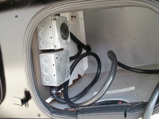
Plug it into the generator outlet in the shore cord compartment................... looks like this, more or less.

original-shore-power-installation-jpg.151944


Then go and get a outlet tester from Harbor Freight, Home Depot, etc..............

63929_I.jpg


Go ahead and get a good extension cord, 14 gauge or 12 gauge, and plug it into the puck adapter, and (with the generator running) take the tester and make sure you are getting lights that indicate 'correct", at the end of the extension cord. You know everything is wired correctly at this point. Go inside the RV and remove the front panel from the power panel, four brown screws.

If you used the tester and didn't get proper lights, say hot/neutral reversed, (SHUT DOWN THE GENERATOR) you will need to open the generator outlet receptacle and check the wires on the back to insure they are wired correctly, with the white and black wires on the silver and brass screws, and the ground on the ground pin screw.


parallax-panel-with-progressive-converter-jpg.151888


Then remove the two hex head screws that hold the panel on that covers the area around the breakers on the upper left. (NO SHORE POWER OR GENERATOR POWER AT THIS POINT, MEANING DO NOT PLUG THE SHORE CORD INTO ANYTHING.)

Note, originally WBO will have wired the refrigerator and the power converter on the same breaker using a ferrule to combine the two wires on the breaker without "double tapping" the breaker. No telling what was done when the new converter was installed. I installed a short pigtail and then wire nutted the fridge and converter wires to the pigtail, as I had no ferrules to combine the wires.

Trace the white/black/green wires that come up from the converter to the breaker and the buss bars on the LH side near the breakers. DO not disturb the black and white wires going to the DC fuse panel on the left. Remove the wires from the breaker and buss bars, and install a plug end on them............


61QhvKvvU8L._AC_SL1385_.jpg


Green on the D shaped ground pin, white on the silver blade (usually wider than the other, and black on the brass blade)

Plug the Kill a Watt in the extension cord, read the volts and hz. then plug the converter into the Kill a Watt and check your DC voltage and see if it is working.

This bypasses everything else.

Lets see if it is charging now.

Charles
 

Attachments

  • original shore power installation.jpg
    original shore power installation.jpg
    148.5 KB · Views: 17
Back
Top Bottom