lithium conversion questions

The friendliest place on the web for anyone with an RV or an interest in RVing!
If you have answers, please help by responding to the unanswered posts.
The DC to DC converter only feeds the lithium house batteries, the alternator continues charging the chassis battery the way it always has. So yes, it goes after the point where the chassis battery is connected to the alternator.

One disadvantage to installing a DC to DC converter is it doesn't let current flow backwards through it, so you won't be able to use a Boost switch to let the house batteries jump start a low starting battery.

Correct. However you could use a pair of jumper cables in a pinch.

I have a complete solar lfp conversion and it all works really well. Converter replaced with a lfp compatible charger, deleted the booster/isolator solenoid, and utilized a victron orion for engine charging to house. Victron stuff is really nice and completely configurable. Chassis battery has it's own 100W solar panel and SCC, but you could also utilize a trickl-start or similar to maintain a starting battery.


DIY 230A Eve cell lifepo4, Xantrex inverter with it's own outlets in the coach. Doing it again I would use a transfer switch right into one of the 120V circuits, and get a 1kW or 1.5 inverter.
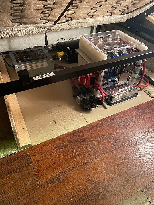


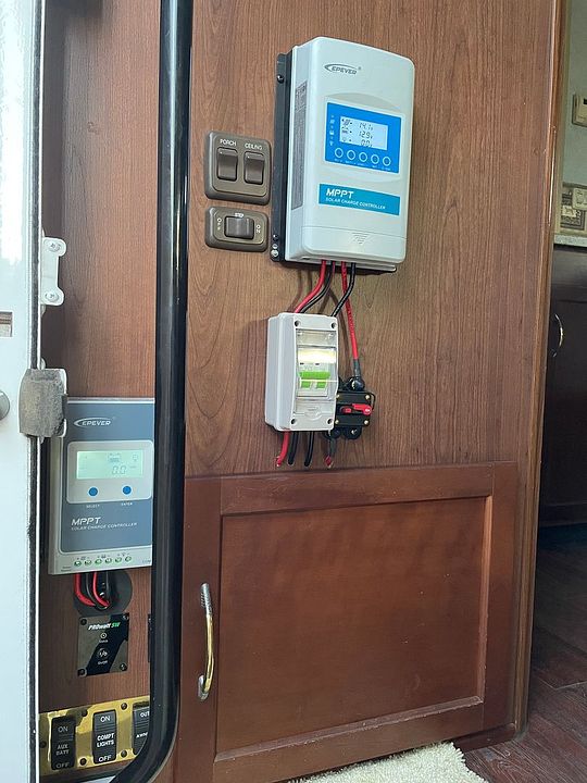
MeanWell makes really nice lfp compatible chargers. The lfp converter never worked right for me. Iota for the FLA's as built, then got a Powermax 55a converter. Seems their voltages just don't work very well for lfp - either too high or too low, and equalization is simply not used with lifepo4. When it's full it's full, you don't over-volt it. 14.2V or 3.55Vpc is ideal.

 
Last edited:
So this discussion is about tow vehicle alternator charging of a 200Ah LiFePO battery. What are the concerns?
1. The voltage drop from the alternator to the battery due to high current draw and small conductor from Alternator to the batteries. Voltage at the batteries will not be high enough to fully charge the LiFePO batteries.
2. Large charging demand from batteries (when depleted) will be constant and over what the alternator can deliver. The alternator may be damaged and potentially overheat and fail.

I can see how an MPPT controller may handle concern #1 but how will it handle #2?
 
A solar controller is not the right device for alternator charging. A dctodc charger is. And a dctodc is generally ignition switch activated - it only turns on when the engine runs.

And yes, the feed wire to a trailer is always of concern. Some use a dedicated cable (heavy wire) for this purpose, based on distance and amperage.

If you have solar then vehicle charging becomes secondary. Same for generator or shorepower. These alternates are for when you don't have sunshine and solar gain. Size house batteries to provide daily usage, preferably for at least a couple of days, unless you're driving every day.
 
I took your mention of a stock inverter to mean a stock converter instead, i.e. you only have one charger along with the engine alternator. Correct?

A DC to DC converter can boost the voltage as well as limit the current going to the batteries so with a little creative wiring it can solve both problems.

Disconnect the stock converter from the fuse board so the board is fed only from the batteries. Run a new line from the converter's output to the input of the DC to DC converter and connect it there along with the charging line from the vehicle's alternator. Take the output of the DC-DC converter to the batteries. The DC to DC converter will boost the voltage from your stock converter as well as limit the current when the alternator is running. It's OK to connect two DC sources together, the one with higher voltage will simply block the current from the one with lower voltage. It's AC where you can't connect two sources together without special precautions.
 
thanks for all the input, I just ordered a kisae DMT1250 50 amp dc to dc converter. I checked into the victron but saw a lot of complaints about it running hot.
 
Just make sure your alternator has enough spare capacity to feed an extra 50 amps.
I got the 18A Victron, does not run hot, does not overload alternator.
 
Correct. However you could use a pair of jumper cables in a pinch.
Make sure the DC to DC converter is off before you connect the cables. If it's on the cables will create a direct short between it's output (the house batteries) and it's input (the chassis battery).
 
You've mentioned using a MPPT solar charge controller with an alternator several times, John. This is the wrong application for it and it will likely damage the controller if you use it to regulate an alternator's output.

MPPT solar controllers are designed to function with solar panels where the current is not much greater into a short circuit (Isc) than at the panel's Maximum Power Point (MPPT). These are both specifications that are stated on the panel so you can choose an appropriate controller.

Alternators don't act this way, they deliver essentially unlimited current into a short circuit. A MPPT controller has a specified maximum input current limit and it can be damaged if you ask it to regulate the virtually unlimited output current of an alternator.

And a MPPT controller only reduces the input voltage as it converts the excess voltage into additional current. It does not transform a low input voltage into a higher output voltage the way a DC-DC converter will.
[
Thanks. Modern Alternators do have current regulation but it's often at 100 amps give or take.. that might indeed be a bit much for an MMPT.
 
I took your mention of a stock inverter to mean a stock converter instead, i.e. you only have one charger along with the engine alternator. Correct?

A DC to DC converter can boost the voltage as well as limit the current going to the batteries so with a little creative wiring it can solve both problems.

Disconnect the stock converter from the fuse board so the board is fed only from the batteries. Run a new line from the converter's output to the input of the DC to DC converter and connect it there along with the charging line from the vehicle's alternator. Take the output of the DC-DC converter to the batteries. The DC to DC converter will boost the voltage from your stock converter as well as limit the current when the alternator is running. It's OK to connect two DC sources together, the one with higher voltage will simply block the current from the one with lower voltage. It's AC where you can't connect two sources together without special precautions.
are you sure the dc to dc will raise the voltage from the 13 from the house charger to the 14 needed for lithium batteries? I have a guy at justanswer saying they can only lower the voltage.
 
A "buck" converter will only lower voltage, a "boost" converter will increase it, and a "buck-boost" converter can do either. So yes, it's possible a particular converter will only lower voltage. If you need either, then a buck-boost converter is what you want.

Mark B.
Albuquerque, NM
 
I have a complete solar lfp conversion and it all works really well.
I would like to comment that your installation could be the poster child for what is the ideal deliberate and well executed system. The attention to detail is impressive, well done.

Mark B.
Albuquerque, NM
 
are you sure the dc to dc will raise the voltage from the 13 from the house charger to the 14 needed for lithium batteries? I have a guy at justanswer saying they can only lower the voltage.
Check the specifications for the DC-DC converter you're interested in. I haven't looked at every one on the market, but every RV or solar DC to DC I've looked at can boost as well as reduce voltage while providing current limiting.

For example, here's the datasheet for a Victron Orion-Tr Smart DC to DC converter. All of their DC to DC converters have similar input and output voltage specs. This one is designed to charge batteries and the 12 volt version shows an input range from 8-17 volts and a low voltage shutdown at 7 volts. Output is nominally 12 volts, adjustable from 10-15 volts regardless of the input voltage. This means it can take an input as low as 8 volts or as high as 17 volts and output whatever voltage you set from 10-15 volts.

https://www.victronenergy.com/uploa...Smart-DC-DC-chargers-isolated-250-400W-EN.pdf
 
i have the abso from kisae. For testing purposes, I currently have the dc to dc hooked to a lead acid battery on a lead acid charger. the dc to dc says its putting 9 amps into the lithiums at a voltage of 13.2 volts. this sounds like its working like you described. the guy at justanswer seemed so sure of himself that dc to dc chargers cannot boost voltage, which is why i was confused.
 
i have the abso from kisae. For testing purposes, I currently have the dc to dc hooked to a lead acid battery on a lead acid charger. the dc to dc says its putting 9 amps into the lithiums at a voltage of 13.2 volts. this sounds like its working like you described. the guy at justanswer seemed so sure of himself that dc to dc chargers cannot boost voltage, which is why i was confused.
Turn off the lead acid charger while the battery is still feeding the lithiums through the DC to DC charger, and see if the output to the lithiums remains constant as the lead acid voltage declines. This will settle the question once and for all.
 
so i let the little 5 amp lead acid charger go for about 24 hours and my one lithium is at 99.1% and the second one that i had connected by jumper cables got to 87%. I assume that means this dc to dc ups the voltage. Now I'm getting conflicting advice as to what to do with the battery isolation manager. Should I just take it out of the loop and connect the chassis battery/alternator cable directly to the dc to dc? And if I do that, will there be an issue with the house converter being connected to that same input. My concern is that the house converter would over charge the chassis battery since it would always be directly connected to it.
 
One thing you don't want to do is connect 2 LiFePo4 batteries that are not balanced with each other on the same circuit, due to their low internal resistance they would try to quickly balance out which could overload the BMS, as well as cause harm to the cells and the wiring.
 
that's what i thought but that isn't what happened. they both started at 47% but ended at 99 vs 87. they were connected to each other the whole time yet they didn't rebalance. After disconnecting the charger, I left them connected to each other and the 99 showed it was losing around 1 amp and the 87 gaining around 1. So I left them connected since it looked like they were rebalancing. When I check back the % hadn't changed much and neither one was gaining or losing to the other. I've since hooked the 87 by itself to the charger to get it up to 99 and then I'll reconnect them to each other.
 

Forum statistics

Threads
132,119
Posts
1,390,614
Members
137,836
Latest member
Stubblejumper
Back
Top Bottom