You are using an out of date browser. It may not display this or other websites correctly.
You should upgrade or use an alternative browser.
You should upgrade or use an alternative browser.
The friendliest place on the web for anyone with an RV or an interest in RVing!
If you have answers, please help by responding to the unanswered posts.
If you have answers, please help by responding to the unanswered posts.
Gary RV_Wizard
Site Team
Once that error in the diagram is corrected (310AH vs 210 AH), all the arithmetic works and Ohms Law is safe.
You can, but that's the "more batteries" that Seilerbird stated. In your case, more sets of 4 batteries, since you have a 24v system. So you have these sets of 4x6v batteries that produce 230AH @ 24v, and you can parallel as many sets as you have room for and bump the AH by 230 for each full set.just appears to me (theoretically) that if 2 batteries in series make one bigger battery, why can't I connect those bigger batteries in parallel to get more AH?
OP
OP
Desert_Rat
Guest
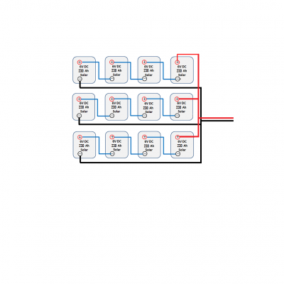
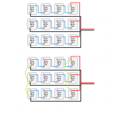
What do you think of the images above your response. Why do you suppose the source has those 2 extra parallel leads and is claiming more AH from it?
"Once that error in the diagram is corrected (310AH vs 210 AH), all the arithmetic works and Ohms Law is safe"
I missed that on first read of your response. I agree.
"Once that error in the diagram is corrected (310AH vs 210 AH), all the arithmetic works and Ohms Law is safe"
I missed that on first read of your response. I agree.
M
markbarendt
Guest
Desert_Rat said:What do you think of the images above your response. Why do you suppose the source has those 2 extra parallel leads and is claiming more AH from it?
The green lines add nothing except redundancy and don't change the math.
Each battery only has 2 terminals, the total amount of energy available from those terminals is limited absolutely by that fact. Regardless of how many ways you wire it, that is an absolute limit.
Any one system can pull 100%, if there are 2 systems attached the systems have to share that 100%, 50/50, 90/10 or whatever.
OP
OP
Desert_Rat
Guest
So you think the source's claim of 310 ah is a typo. I think that makes more sense but I'd still like to know why the 2 parallel leads are added. What's the point of that?
M
markbarendt
Guest
Electricity is like black magic for the untrained, the extra leads are a form of wishful thinking.
prfcdoc
Well-known member
Yes sir! My thought as well.markbarendt said:Electricity is like black magic for the untrained, the extra leads are a form of wishful thinking.
OP
OP
Desert_Rat
Guest
markbarendt said:Electricity is like black magic for the untrained, the extra leads are a form of wishful thinking.
With that I'll assume you mean the source believes the bank is better balanced by doing it in that manner. The source is theoretically correct but I agree that it seems overly redundant.
M
markbarendt
Guest
No, the green drawn in wires do nothing extra. Zero, zip, zilch, nada, squat... The green wires have no value and should not be used IMO.Desert_Rat said:With that I'll assume you mean the source believes the bank is better balanced by doing it in that manner. The source is theoretically correct but I agree that it seems overly redundant.
The source is not correct.

M
markbarendt
Guest
One way to think of "a battery bank wired in series" is as "a single battery".
Bear with me Desert_Rat.
The batteries you are using are made up of smaller 2-volt batteries (cells).
To build a 6-volt battery one simply puts three 2-volt batteries (cells) in a box and then wire them in series.
A 12 volt battery can be built in the same manner by simply putting six 2-volt batteries (cells) together, a 24-volt battery is a collection of twelve 2-volt batteries (cells) wired in series.
The number of boxes the 2-volt batteries (cells) are housed in is irrelevant.
Whether the bank is wired internally or externally is irrelevant.
Any bank that is wired in series effectively acts as a single battery.
Gary RV_Wizard
Site Team
About the most you can say for the 4 green wires is that they may be shorter than the blacks & reds that make the same electrical connection. Maybe that helps balance the loading by providing a slightly lower resistance alternate path, but that's true only if the Reds & Blacks are undersize or just marginal in size.
OP
OP
Desert_Rat
Guest
"Good morning Robert,
Thank you for the email, I can confirm that indeed we have made a typing error on the website which we will fix right away. The correct value should be 210Ah and not 310Ah as indicated on the website. I personally thank you for bringing it to my attention.
I do hope that the rest of the website content is of great value to you Robert and please feel free to alert me to any other discrepancies you may find on the website, it will be greatly appreciated.
Best Regards"
Your schematic shows a 4 in serie first, then a 3 in parallel, 3S4P.
There is also the 3 in parallel first, then 4 in serie, 4S3P.
In your 3SP4, take in account that if any of the battery/cell fails, the whole string in this 4S will be faulty, not supplying anymore, turning into 2S4P
In a 4S3P, if a battery fails in a 3P, the impact is less, the 2 others in the 3P go on supplying.
(Batteries are the same model, considering having the same voltage/SOC in any 3P)
Also, you could add diode insulation and fault protection, by adding diodes (good amperage) isolating the 4 (3S4P), or the 3 (4S3P), for both charging and discharging. Not very costly.
The advise is also to add fuses (good amperage) in the battery to converter, unless already in the converter setup.
If you stick with your 3S4P schematic, the batteries voltage in any string can vary independently of each other, and in the long run, it is always safe to monitor the voltage of each battery, even with a very simple battery monitor.
The green lines are outlining the idea of a "bus bar" type connection, it is better being shorter, linking each string. The negative/black line then just need one connection to this green "bus bar".
OP
OP
Desert_Rat
Guest
354P, 453R? Sorry, I don't understand this terminology. I understand the gist and will look into implementing it. Also, further explanation of diode use would be appreciated.
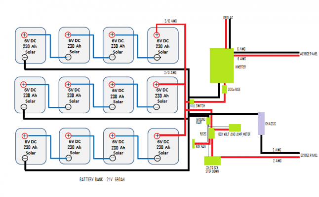
The attached image is what I have so far. Again, PV is not in yet, will be in a month or so and will be 2040w.
Products:
Deca GC15: http://www.dekabatteries.com/assets/base/0248.pdf
AIMS 120/24/3000: https://www.amazon.com/AIMS-Power-PICOGLF30W24V120VR-Inverter-Charger/dp/B00NLLSGMY/ref=sr_1_1?s=automotive&ie=UTF8&qid=1484791027&sr=1-1&keywords=AIMS+Power+PICOGLF30W24V120VR+24V+Pure+Sine+Inverter+Charger
AIMS 24 to 12v step down: https://www.amazon.com/AIMS-Power-CON40A2412-Amp-Converter/dp/B01JIZWX52/ref=sr_1_1?s=automotive&ie=UTF8&qid=1484791122&sr=1-1&keywords=AIMS+Power+CON40A2412+40+Amp+24V+DC+to+12V+DC+Converter
Ammeter: https://www.amazon.com/bayite-6-5-100V-Display-Multimeter-Voltmeter/dp/B013PKYILS/ref=sr_1_1?s=hi&ie=UTF8&qid=1484791435&sr=1-1&keywords=bayite+DC+6.5-100V+0-100A+LCD+Display+Digital+Current+Voltage+Power+Energy+Meter+Multimeter+Ammeter+Voltmeter+with+100A+Current+Shunt
Cables, terminators, fuses, etc also via Amazon.
Attachments
OP
OP
Desert_Rat
Guest
edit: Larger http://imgur.com/a/Z8eAh