New Project, Solar for Class C

The friendliest place on the web for anyone with an RV or an interest in RVing!
If you have answers, please help by responding to the unanswered posts.
I spent most of the night working on the Bubba Edison Version 2.0 replqcement AC power generating system.

Years ago when I replaced the Norcold refer with a residential model in my DP, I saved the Stainless Steel door inserts thinking I might use them someday for something.

Tonight I found a use for one of them.

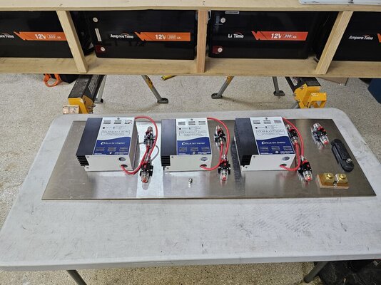
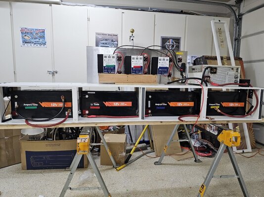
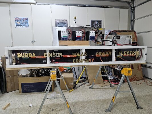
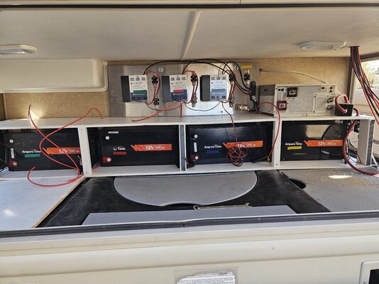
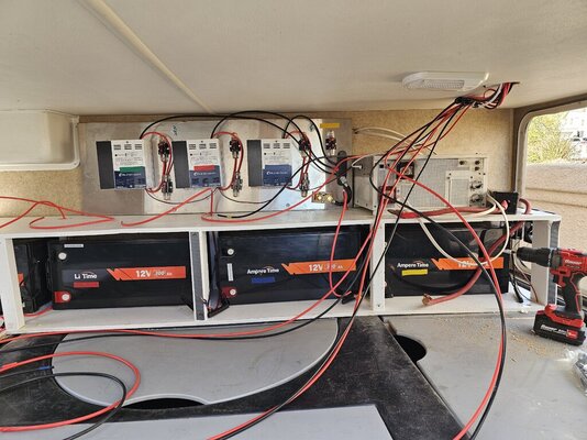
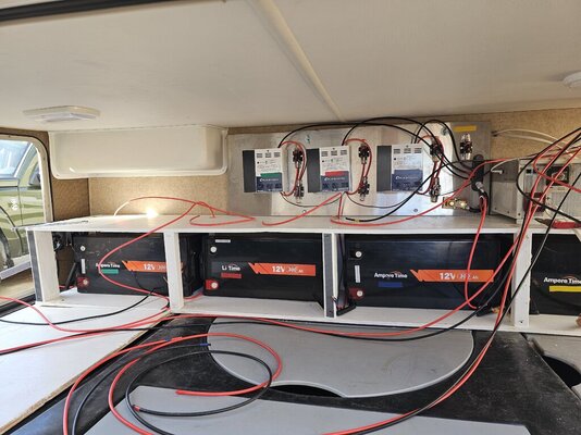
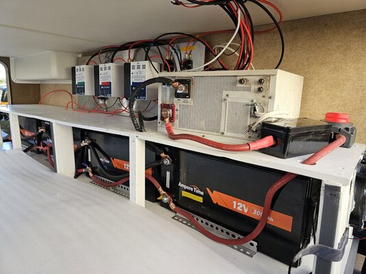
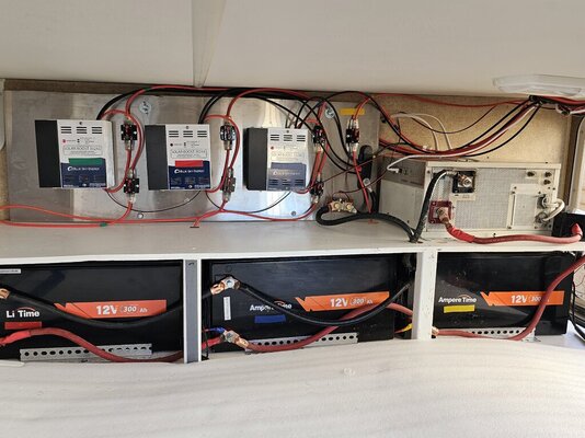
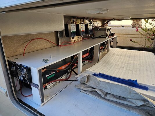
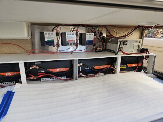
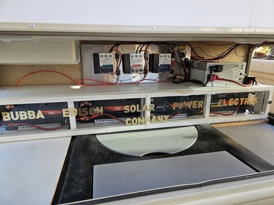
I mounted three of the four charge controllers, input and output DC circuit breakers, and the shunt for the battery monitor on the stainless steel panel.

Solarman, has mentioned the advantage of mounting on metal for heat dispersion.

The other controller is the Master controller and these three are networked as slave controllers.

The Master controller is recessed into the wall in the bedroom like before with the battery monitor next to it.

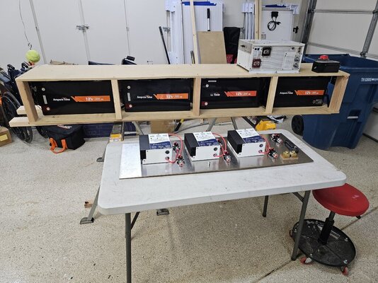
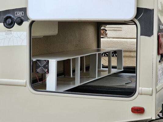
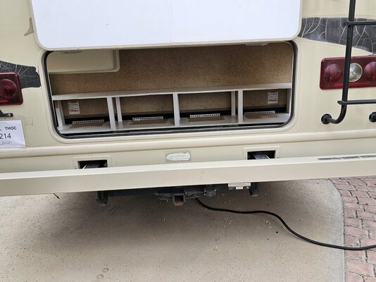
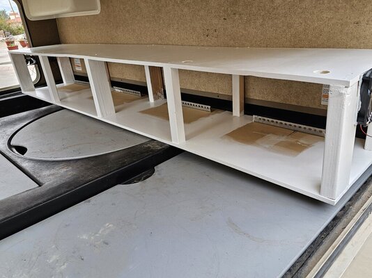
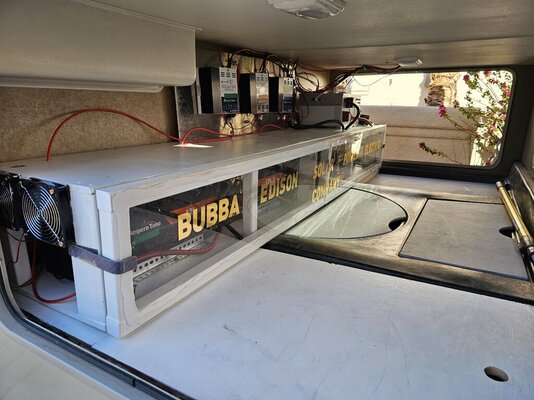
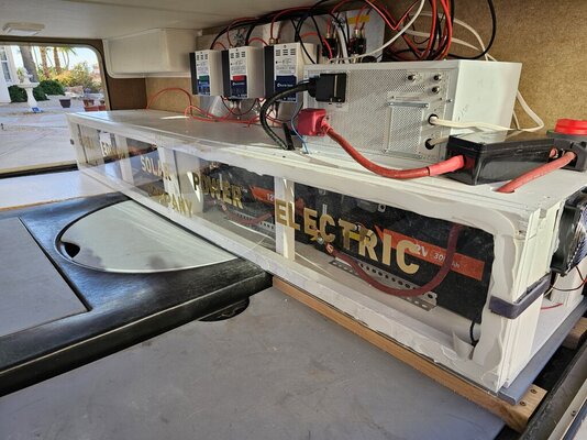
It will hang this equipment panel with a J channel on the wall of the rear storage compartment above the four batteries.

Without pictures...well you know the rest.

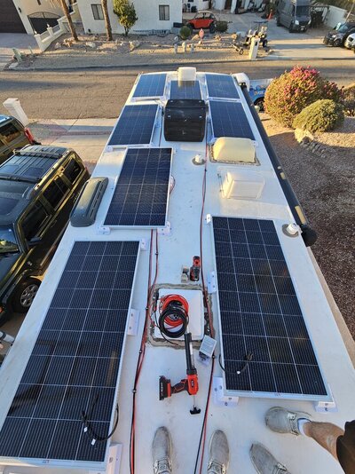
Love the big rubber 'persuader' on the R side of the bench. They make everything fit so much better. 😊 I am surprised to see a corded drill, however. 😁
 
The "Persuader" was to coax a tight fitting bolt into a hole.

I usually use two drills when working so that one can have a drill bit and the other can have a screwdriver attachment so that I do not have to change them back and forth.

There is a battery operated drill to the right of it.

The corded drill was needed because my entire bag of Milwaukee tools was in the fire.
 
More progress:

This afternoon and evening I got a lot accomplished.

I built the enclosed shelf and test fitted the components. I will figure out where to run the wires and cables. The batteries are easy, a solid straight black line across the top and a red line across the bottom.

The equipment that is mounted to the stainless panel will hang on the wall above the shelf and to the left of the Invertor.

I am not sure yet, but I think that I will leave the Invertor exposed on top of the shelf for cooling.

The battery section is like a wind tunnel with pusher fans on the left and puller fans on the right.

I will put the vent grates on the side doors with inside plexiglass covers for winter.

I am going to have a 90 inch by 11 inch detachable front plexiglass panel in front of the batteries with the following in gold letters.

BUBBA EDISON SOLAR ELECTRIC POWER COMPANY VER 2.0

Once I figure out where all the holes need to be I will remove the parts and paint it white like before.

Here are some pictures of the empty storage compartment and the components.
Wow! That is some major construction! I'll be interested to see the finished product. 😊
 
New enhancement to the project:

Because it is so much easier for me to wire and connect all the equipment while sitting comfortably and working at the work table, I am going to wire everything and connect the final controller panel to the wiring from the solar panels with Anderson connectors mounted in the rear storage compartment.

The connection of the cables from the solar panels will be thru a wall mounted Anderson plug in socket in the rear compartment and the controller panel input cables will have the Anderson plugs attached so they can just plug into the wall.

Kind of like plugging a power cord into a socket in a house. There will be four of them, one for each controller.

This will make it a plug and play installation.

The output from the charge controllers will simply be four 10 ga positive red cables with lugs to connect to the batteries and a single 2,0 ga cable from the negative buss bar, then thru the shunt and to the common black negative battery connection.

This I can handle. I do not think that I could spend an hour making all the controller connections in the cramped storage compartment.

Here is a link to the connectors I am using.


Attachments

  • 20231220_231041.jpg
    20231220_231041.jpg
    184.2 KB · Views: 12
Last edited:
Buy the way:

Here are the latest pictures of the mock up and test fitting of the components.

The controller panel will hang vertically above the shelves holding the batteries.

The Invertor will be on the right side.

And the front plexiglass safety shield will cover the front of the batteries like the old system.

I was going to put, "Version 2.0". in gold letters but there were no numbers in the lettering I got online.
 

Attachments

  • 20231220_231035.jpg
    20231220_231035.jpg
    209.7 KB · Views: 15
  • 20231222_131416.jpg
    20231222_131416.jpg
    119.8 KB · Views: 14
  • 20231222_131455.jpg
    20231222_131455.jpg
    150.7 KB · Views: 12
  • 20231222_131505.jpg
    20231222_131505.jpg
    153.6 KB · Views: 13
  • 20231225_043236.jpg
    20231225_043236.jpg
    213.3 KB · Views: 15
Another update:

Tonight I worked on finalizing the layout with a full mock up of the items that will be in the rear storage compartment.

I had to build lots of battery cables and get the solar cables ready.

I need to get about four feet of 2/0 welding cable. I had a 50 foot roll but I used it all up between Bubba 1.0 and Bubba 2.0.

I have two guys lined up to do all the roof projects on Thursday. We will install all the solar panels, install three Maxxair vent covers, two Venturi plumbing vent exhausters, and remove the over the air antenna as it is in the way of one of the panels.

I ordered one of the new model StarLink antennas.

I still have to mount the Master controller for the IPN network, the Pro Monitor Battery monitor. and the Zanbus system control panel. They are going to be flush mounted in the wall of the closet next to the rear bed.

I also still need to install the Automatic Generator Start, but I am not is as much of a hurry because the new system has 25% more battery capacity.

The last piece of the project is to intercept the 120 volt romex line from the transfer switch and reroute it thru a 30 amp circuit breaker to the Invertor. From the invertor, a 120 volt line runs to another 30 amp circuit breaker and on to the 30 Amp main electrical panel.

This is the same way as I did it before. This allows the seamless and constant operation of 120 volt electricity when on shore power, generator, or the Invertor powered by the battery bank.

Nothing has to be done to switch over from one to another of the three sources of power.

Here are the latest pictures of the mock up with and without the safety shield,

I had to put a wood block under the vertical controller panel to hold it up for the pictures.
 

Attachments

  • 20231227_020849.jpg
    20231227_020849.jpg
    201.1 KB · Views: 14
  • 20231227_021106.jpg
    20231227_021106.jpg
    205.2 KB · Views: 14
Last edited:
Update:

We just finished installing the eight 200 watt panels on the roof. I also had them install the Maxxair covers for the roof vents.

I am so tired that I can barely type.

Here are two pictures, a before and after shot of the roof.
 

Attachments

  • 20240104_121312.jpg
    20240104_121312.jpg
    121.4 KB · Views: 15
  • 20240104_170311.jpg
    20240104_170311.jpg
    243.3 KB · Views: 15
I am almost finished with this project.

I have installed everything except for connecting the eight solar cables, (four black and four red from the panels) to their connection at the top of the charge controller panel. I also have to connect the battery cables to the four batteries.

I climbed into the storage compartment to finish the connections and I could not get anywhere near comfortable enough to connect them. I am to old to sit cross legged or on my knees.

So I will hunt up someone to connect them while I make sure that the are connected correctly.

Here are the latest progress pictures.
 

Attachments

  • 20240106_123945.jpg
    20240106_123945.jpg
    146 KB · Views: 12
  • 20240106_134338.jpg
    20240106_134338.jpg
    179.4 KB · Views: 12
  • 20240106_134341.jpg
    20240106_134341.jpg
    157.7 KB · Views: 12
OK, I got a surge of energy and actually climbed into the storage compartment to finish the system.

I used the foam pads that came with the panels to cushion and allow me to do the work.

I finished up every connection and first turned on the charge controllers to charge up the battery bank. It was at 13.5 volts when I turned them on.

I then turned on the Invertor/charger and ran into a problem. The Invertor had two fault codes, (F47 and F48). These indicated low voltage from the battery. I knew that the voltage at the batteries was 13.5 so I measured it at the input to the Invertor again at 13.5 volts.

After some more research and a consult with Lou, I believe that the Invertor was in fact damaged in the fire.

The choices were to tear into the Invertor and troubleshoot it or just buy a new one.

For me it was not a hard decision. I tried to find one locally but I had to order thru Amazon with a delivery date between the 17th and 19th.

I lost the red and black plastic covers for the DC input. I guess this is an expensive way to get replacement covers.

I still plan on going to Q. Hopefully with a functional system.

Here are some pictures of the finished project without the safety shield to see it better.
 

Attachments

  • 20240108_155227.jpg
    20240108_155227.jpg
    176.4 KB · Views: 8
  • 20240108_155246.jpg
    20240108_155246.jpg
    163.4 KB · Views: 7
  • 20240108_155322.jpg
    20240108_155322.jpg
    176.6 KB · Views: 8
  • 20240108_155329.jpg
    20240108_155329.jpg
    151 KB · Views: 8
Last edited:
Bubba Edison 2.0 is finally finished and fully functional.

I just finished installing the new Invertor/charger.

The Invertor function works, the pass thru function works, and the charger function is putting 115 amps into the batteries.
 

Attachments

  • 20240114_152824.jpg
    20240114_152824.jpg
    148.6 KB · Views: 7
  • 20240114_152832.jpg
    20240114_152832.jpg
    159.7 KB · Views: 7
  • 20240114_152842.jpg
    20240114_152842.jpg
    188.2 KB · Views: 7
Back
Top Bottom