CharlesinGA
Well-known member
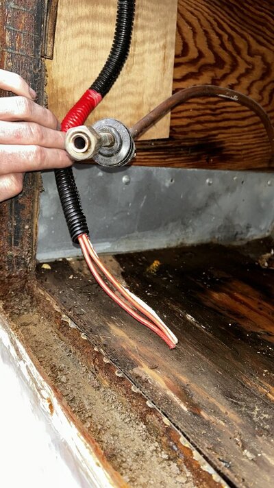
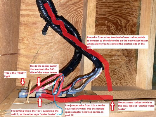
Two of those red wires have the words "water heater" printed on them. Bottom pic, far left has a red wire and a white wire on what would be the fault light. The white is 'most likely' the ground, and the red would be the blue off the water heater that powers the fault light (12v voltage coming back from the control board on the heater to operate the light)
The next two red wires would be on the water heater switch. One wire would be a 12v positive from somewhere 'most likely' the 12v fuse panel, fuse #5 which has a red wire, and is the "water pump/appliances" fuse. The other red wire is going to the water heater to connect to the brown on the old heater, and on the new one, that same wire will connect to the ORANGE wire (the on heater wiring switched from brown to orange for the gas control)
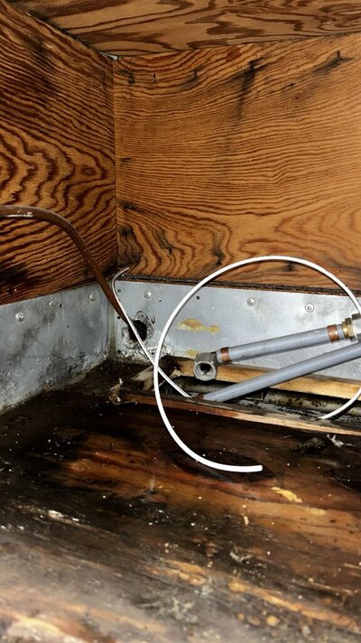
I would suspect that is the original wiring on the motor home, but am blow away by the heavy wire that was used and the 20 amp fuses, crazy actually for something that does not use but one or two amps.
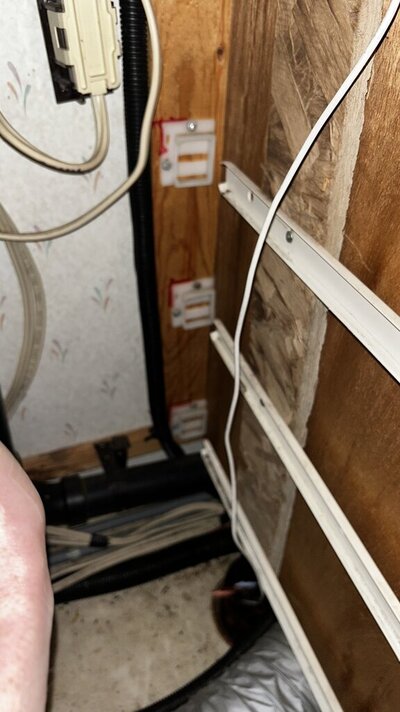
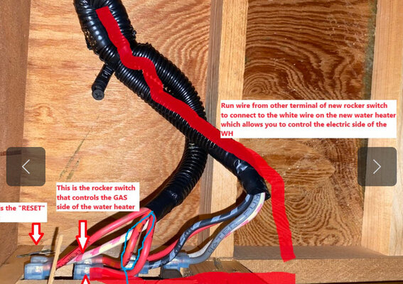
Question, do you think you would be able to run one more wire from the area behind the switches to the water heater? It would only need to be 16 gauge. Rocker switch like this would be good as it has a base to mount it. Rocker switch link. My suggestion is what is annotated in the pic of yours below.
Edit: You must verify which terminal is hot all the time, and which is hot only when the switch is on. You want the one that is hot all the time.

The next two red wires would be on the water heater switch. One wire would be a 12v positive from somewhere 'most likely' the 12v fuse panel, fuse #5 which has a red wire, and is the "water pump/appliances" fuse. The other red wire is going to the water heater to connect to the brown on the old heater, and on the new one, that same wire will connect to the ORANGE wire (the on heater wiring switched from brown to orange for the gas control)
I would suspect that is the original wiring on the motor home, but am blow away by the heavy wire that was used and the 20 amp fuses, crazy actually for something that does not use but one or two amps.
Question, do you think you would be able to run one more wire from the area behind the switches to the water heater? It would only need to be 16 gauge. Rocker switch like this would be good as it has a base to mount it. Rocker switch link. My suggestion is what is annotated in the pic of yours below.
Edit: You must verify which terminal is hot all the time, and which is hot only when the switch is on. You want the one that is hot all the time.
Attachments
Last edited: