You are using an out of date browser. It may not display this or other websites correctly.
You should upgrade or use an alternative browser.
You should upgrade or use an alternative browser.
Wiring diagram for travel trailer - need advice
- Thread starter bighugetrout
- Start date
The friendliest place on the web for anyone with an RV or an interest in RVing!
If you have answers, please help by responding to the unanswered posts.
If you have answers, please help by responding to the unanswered posts.
Ex-Calif
Well-known member
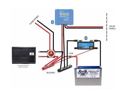
Not sure what's the intention of the 3-way switch. As diagramed it appears you want it to switch the 120V shore power on and off "and" switch the 12V converter power to the buses on and off. The only way the converter will work is if that switch is in the "All" position and it's also not a good idea to use that kind of switch for AC power.
I presume the shore power goes through a power cabinet with breakers so the diagramed switch is not needed on the shore power side. There should be a circuit breaker for the AC supply to the converter. BTW - Is it also a charger? It would make sense if it was.
I would install a simple on an off switch between the DC positive buses (or negative) and the battery(ies)
If I wanted to be fancy I would install an ACR (automatic charge relay) between the solar supply and the batteries. The ACR would only close if you have solar generating.
I am also assuming that the house 12V supplies will be on the same DC buses diagramed and that all the house circuits are fused through a fuse panel.
JayArr
Well-known member
You've got your ac and dc mixed. Shore power is AC and the Battery is DC, the switch will apply AC to the battery - that's no good.
I think you want a transfer switch to select power from one of two sources (Shore power, or Inverter) and output it to the RV outlets.
On the DC side, the charger/converter, solar panel charge controller and battery input to the inverter are all connected.
You don't show a charger for shore power, is that on purpose?
bighugetrout
Member
JayArr
Well-known member
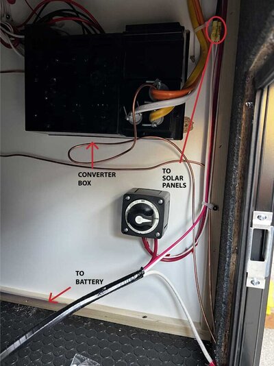
Why are there multiple AC wires connected to the "Converter Box"?
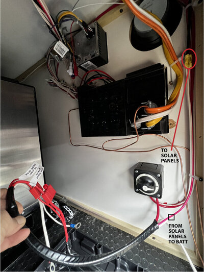
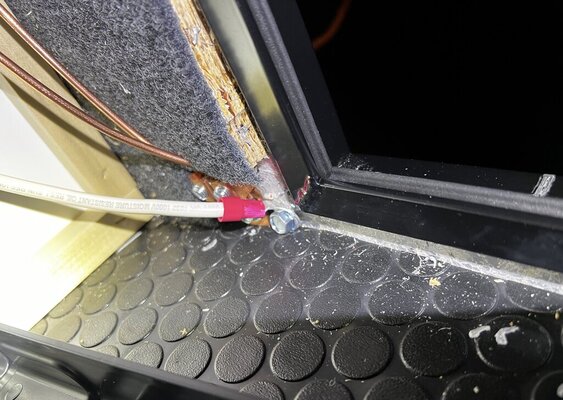
I can't see from the picture where all of the battery wires are coming from and I'm a little confused:
The white sheathed wire with two red wires in it that heads down through the floor - where does it go?
There is a large red wire and a smaller white wire that comes down the wall and loops up into the switch - where is it from?
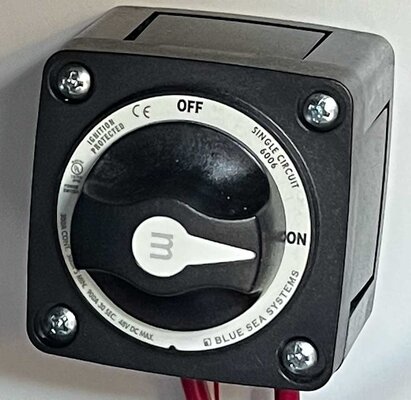
Can we get a closer picture of the switch? I can't read the writing from the pic you've posted.
I can't see from the picture where all of the battery wires are coming from and I'm a little confused:
The white sheathed wire with two red wires in it that heads down through the floor - where does it go?
There is a large red wire and a smaller white wire that comes down the wall and loops up into the switch - where is it from?
Can we get a closer picture of the switch? I can't read the writing from the pic you've posted.
bighugetrout
Member
bighugetrout
Member
The trailer manufacture wired outside plug for solar using panel that has the controller built-in. I'm installing two 100w panels on roof.
Ex-Calif
Well-known member
What is the model number of the PD converter? I am assuming it is also a charger?
The switch you have appears to be only an on off switch for the solar. I am presuming the smaller pair of wires goes to the shunt at the battery?
Is the shunt already installed or are you adding it?
The switch you have appears to be only an on off switch for the solar. I am presuming the smaller pair of wires goes to the shunt at the battery?
Is the shunt already installed or are you adding it?
John From Detroit
Well-known member
Shore power goes to the 120 distribution panel (Breaker box) #1 and one of the branches off i to the INPUT on the Progressive Dynamics converter (Good choice by the way) Dump the switch and connect as follows
Solar panels to solar charge controller to bus bars
Progressive Dynamics out put to bus bars
Batteries to Bus bars
12 volt distribution panel to bus bars
NOTE all connections to bus bars via proper size fuse
IF you add an inverter.. Connect it DIRECT to the batteries (not to the bus bars) and it feeds 120 volt panel 2.. Now you may put a switch between the inverter and a brach on panel one.
OR an automatic switch might be used or be part of the inveerter.
CONVERTER (The PD box) takes 120 volt and makes 12 (Well 13.6 to 14.6) out of it to charge/maintain the batteries.
Solar charge controller takes the output of the panels and makes 13.6 - 14.6 same as the PD box), They can be parallelled no problem.
INVERTER: takes battery power and makes 120vac (Inverse of a Converter)
Hope this helps.
One other thign.. The built in charge controller the trailer builder put in... MIGHT, or Might not, be big enough for a 100 watt panel.. Some of them are only small 10 watt or less. Some are ... better. .You will need to know the specs on it.. And the wire size feeding it. for two 100 watt panels you need some fairly serious wire for best charging.
bighugetrout
Member
Thanks John!
bighugetrout
Member
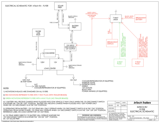
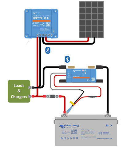
I've attached electrical schematic for my trailer and the wiring diagram suggested by Victron using their components. I'm confused on how to meld the two and have everything work as is. The converter has a switch that can toggle between "acid battery" and "lithium". Thanks again for the help.
Attachments
Ex-Calif
Well-known member
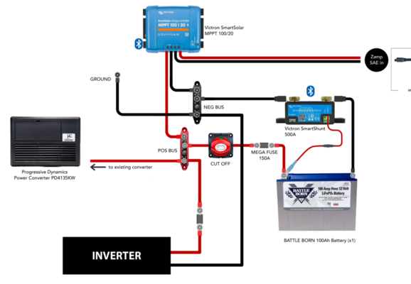
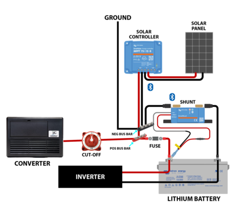
Electrically this should do it. It's not far off the two diagrams you posted.
1/ When switched to "1" you will get solar power charge. When switched to "2" you will get Tow vehicle charge power. When switched to all you will get both.
2/ With shore power available you will get 12V charge from the converter all the time.
3/ Note in this system there is no way to completely shut off the 12V bus without disconnecting the battery. If you want to shut the battery power off with one switch that can be done. You can also repurpose you current single on/off switch for that.
3/ Safety Note!!! --> Do you currently have those two copper ground wires hooked up to the trailer frame from the AC grounds? If so that's a big problem. The copper grounds should be tied together and then tied into the Neutral bus on the AC panel.
Otherwise if you short a circuit internally on any appliance the trailer frame becomes the ground path for 120V AC and that's a bad thing.
Mark_K5LXP
Well-known member
Pretty sure that trailers should not have ground and neutral connected. Should only get their neutral-ground bond at the service panel (where it's being plugged into).
Mark B.
Albuquerque, NM
Mark B.
Albuquerque, NM
bighugetrout
Member
Ex-Calif
Well-known member
Pretty sure that trailers should not have ground and neutral connected. Should only get their neutral-ground bond at the service panel (where it's being plugged into).
Mark B.
Albuquerque, NM
You could be right but it does not make sense to me. The trailer AC panel is a sub panel. The trailer is not "grounded" to earth. If there is a leak to ground (trailer frame) that makes the trailer frame live looking for a path to earth.
If the N and GND are bonded a leak to GND will pass back through N, through the shore panel and somewhere on the shore side find it's way to ground.
Maybe an AC contractor wiz can clarify. FYI my converter/charger ground strap is tied into the N bus on my Class A panel.
PS --> To the OP --> I just noticed on my schematic I did not sketch in the negative wire from the MPPT. If there is a DC negative bus it should be tied in there or alternately if the trailer is using the frame as a ground bus it needs to be grounded to the frame.
Mark_K5LXP
Well-known member
You want the ground point to be as close to the power source as possible. Being plugged into a service panel that does have neutral and ground bonded, then that would be the the path for fault current. While google isn't the final word, a quick search confirms this with lots of hits. A separate discussion is when a different power source than shore is used (inverter or genset). In those cases it will depend on the construction of the source - grounded vs isolated frame.If there is a leak to ground (trailer frame) that makes the trailer frame live looking for a path to earth.
Mark B.
Albuquerque, NM
bighugetrout
Member
Ex-Calif
Well-known member
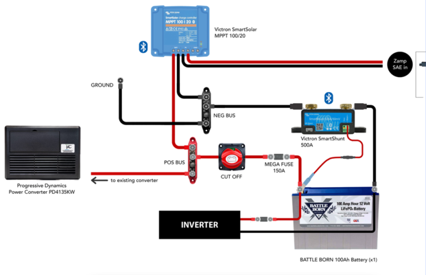
Here's my final wiring diagram. Is the inverter in the right place?
If you want to measure the amps used by the inverter you need to attach the ground to the DDC ground bus on the other side of the shunt. Right now the inverter will bypass the shunt.
In order to measure all the current there should be nothing between the shunt and the negative post of te battery.
Ex-Calif
Well-known member
You want the ground point to be as close to the power source as possible. Being plugged into a service panel that does have neutral and ground bonded, then that would be the the path for fault current. While google isn't the final word, a quick search confirms this with lots of hits. A separate discussion is when a different power source than shore is used (inverter or genset). In those cases it will depend on the construction of the source - grounded vs isolated frame.
Mark B.
Albuquerque, NM
Here is a pretty good article on AC bonding/grounding/earthing.
RV Electricity – The ABCs of campground power and grounding – Part 2
by Mike Sokol Dear readers, As promised, here's Part 2 of the ABCs of RV grounding. But first you should re-read Part 1, since we'll be going over more
 www.rvtravel.com
In the first diagram note that the ground/earth is outside the RV at the transformer end.
In the second diagram you are looking at an RV post box/sub-panel with the N and G separate as they should be with a separate EGC.
In reading the text however I was reminded that the earthing rod is not what trips the circuit breaker in a ground fault. I it is the "imbalance" of current on the L and N legs.
He talks about lightning strikes in RVs and boats and I was also reminded that we bonded the mast to the keel in boats. This was for lightning pass though into the water.
We were at the club bar one day and we saw a practice boat get struck. 20 minutes later it sunk. The lightning had jumped from the mast to the hull and blew 2 baseball sized holes in the hull.
pics or it didn't happen - LOL...


bighugetrout
Member
If you want to measure the amps used by the inverter you need to attach the ground to the DDC ground bus on the other side of the shunt. Right now the inverter will bypass the shunt.
In order to measure all the current there should be nothing between the shunt and the negative post of te battery.
Thanks! Revised.