Onan RV GQ 4000 plug wires chewed

The friendliest place on the web for anyone with an RV or an interest in RVing!
If you have answers, please help by responding to the unanswered posts.

Papa1947

Active member
Joined
Aug 9, 2022
Posts
29
Location
Garden Home Oregon
I thought I saw what I wanted in the manual but can not find it.
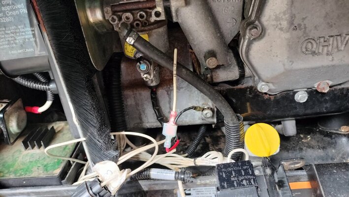
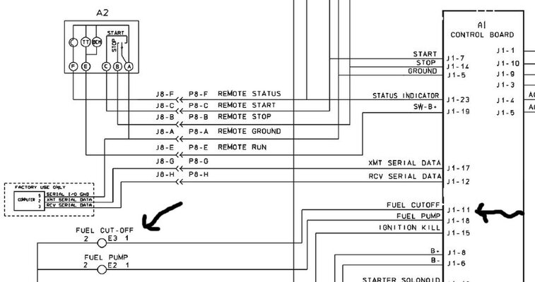
There is a plug for the start button on the generator and the other end plugs into to a harness that goes to the remote panel.
The plug at the generator is numbered 1-8 and the other end is A-H.
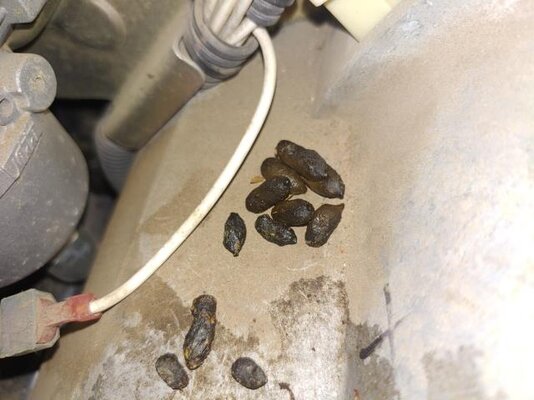
That end was chewed by rats and I need to see the diagram that shows where they go. I saw it a few days ago and thought it was in one of the PDF files I have but can not find it.

Any help would be appreciated.

Gary
 
Go back to the PDFs I provided in the older post. It's in the part 3 of 3 at the very end
 
Go back to the PDFs I provided in the older post. It's in the part 3 of 3 at the very end
I searched your files and all the ones that Cummings sent me including the complete manual that they use to put them together. If you do not mind can you highlight the area on your file and post the image here.
 
Here is the PDF
 

Attachments

  • ONAN Installation Manual schematic.pdf
    41.8 KB · Views: 7
hope this is what you are looking for. I made a jpeg out of PDF

View attachment 156552
I am not sure where the wires are coming off the start switch and going to the remote switch. I have built power supplies and controllers for my CNC milling machine and had not problems but these files are jus not marked in a way to find what I am looking for. Can you mark it ups and show the wires out from the start switch on the generator and then hook up to the plug going to the remote start button?
 
You have all I can give you. I don't think I can walk you through this process via this forum if you are unable to make out the schematics I have posted. The schematics are copies of copies and poor quality so maybe that is the problem. There are 2 schematics that are pertinent. I will post them again here and try to walk you through as best as I can.

Schematic one is below. Look at the legend on the right side where the different components are identified. A2 and A3 are the two REMOTE CONTROL versions available to you, I don't know which one you have. As you can see, there is a wiring harness that goes to A1 (CONTROL ASSY).

Now look at the second page and find S1 (SWITCH START STOP) and follow the wiring.

As you can see, you need to look at the legend on the right and identify what you are looking for and find it on the drawings and just follow the wires.

ONAN Installation Manual schematic 1.jpg
ONAN Installation Manual schematic 2.jpg
 
I am not sure where the wires are coming off the start switch and going to the remote switch.
I think that if you print that page first you can probably magnify it or possible take it to an office supply that can make a zoomed in copy of it for you. I have dont that in other situations with drawings to enlarge them.
 
All he has to do is download the PDFs I attached and open the files in his computer, the computer can zoom in to any location.
 
All he has to do is download the PDFs I attached and open the files in his computer, the computer can zoom in to any location.
I have the pdf files that Onan Cummins sent me. I have discovered that when they assembled the unit they have one wire out of place. They show the number 8 wire from the local going to the F slot on the plug the plug going to the remote. But the connection going to the remote is the H.
I know have it working on the inside.
Next problem is finding the hot wire going to the gas shut off solenoid on the bottom of the carb.
This is a mystery as there should be the other end of just hanging there because they chewed it leaving about 2 inches of wire at the end I have.

Thanks for the help and I am sure your image had it all but I just could not see it. Plus I was hoping to see the actual plugs along with the wires.

Here is the hot wire for the solenoid.
 

Attachments

  • solenoid wire chewed.jpg
    solenoid wire chewed.jpg
    137.7 KB · Views: 6
So I marked up the wiring on this jpeg. That wire goes into a big harness that takes it back to a pair of mating connectors, J1 and P1. J1 then goes to the control electronics and uses pin 8. Go back to the control electronics A1 and look for the big harness and follow it till it gets to the pair of mating connectors. On the going away side, look for pin 12 and pull on it.

ONAN Installation Manual schematic 2A.jpg
 
So I marked up the wiring on this jpeg. That wire goes into a big harness that takes it back to a pair of mating connectors, J1 and P1. J1 then goes to the control electronics and uses pin 8. Go back to the control electronics A1 and look for the big harness and follow it till it gets to the pair of mating connectors. On the going away side, look for pin 12 and pull on it.

View attachment 156593
 
This is my nephews generator and he took this picture for me. Yes he has critters in his as well. I see what I think is that same harness and have peeled the loom back an there are not loose wire.
But I have a feeling these are not all put together the same. Depends who is doing it at the factory.
I have one of those inspection cameras and behind all of this I think I see the plugs you are talking about.
Does this photo sound like what you are talking about?
 

Attachments

  • Milo's generatro.jpg
    Milo's generatro.jpg
    40.4 KB · Views: 5
At this point, just run a new wire to the control electronics and bypass all of the hidden cables and splice it at A1-8. If this gets it going, then you have a decision to make as to how much effort you want to put into it.
 
Are those connectors where you can reach them or does the generator need to be removed from motor home? It is dark now and I will check tomorrow.
Very happy that I have the remote start back. Kind of strange that there are 7 wires going into the harness that goes to the remote start but only 4 wires going to the inside switch. Must be for other options I do not have.
 
I have no idea about where anything is. All of my advice is based on looking at documents. If I was standing next to it I might be more useful
 
At this point, just run a new wire to the control electronics and bypass all of the hidden cables and splice it at A1-8. If this gets it going, then you have a decision to make as to how much effort you want to put into it.
So pulling the computer board seems to be the easier option and was kind of figuring on that. Knowing it is pin 8 is a huge help
 
Another way is to simply add a 12v switch and manually control it
Yes I have thought about that as well. It seems mine is not exact same wiring as what you have shown me.
I have the one that goes to mine and the pin connections are not the same on the A1 board.
This is the wiring diagram for mine.
 

Attachments

  • fuel cut off.jpg
    fuel cut off.jpg
    120.7 KB · Views: 3

Latest posts

Forum statistics

Threads
131,670
Posts
1,382,720
Members
137,455
Latest member
MtnRV
Back
Top Bottom