Progressive Dynamics converter

The friendliest place on the web for anyone with an RV or an interest in RVing!
If you have answers, please help by responding to the unanswered posts.

PancakeBill

Well-known member
Joined
Apr 9, 2005
Posts
6,878
Location
Benson , AZ.
Need the hive. I have the above converter in my truck camper, it is the 6300 series model 6332. I am gettin high DC voltage out of this. I replaced the 30 amp plug, 1 because it looked like crap and 2 because I thought maybe bad grounding lug. Actually the inside looked fine, but new one on now. One question bugging me, if I check for continuity between the neutral and ground, I was expecting to see it. There is none. I then went to the other end, the converter, mainly because the next step into the camper is way back under the counter. The ground wire is nice and tight and clean, the neutral same to its buss bar, and the hot goes to the CB main. In morning I will back off and retighten all those connections. With converter on I see 13.3 to battery. but I see 15.8 to the DC feed for lights, pump etc.

Seems like issue of a bad ground, but it may also be a bad converter. Thoughts? If concensus is bad converter, does anyone have a spare to sell?

The last connection I have not looked at yet is outside wall under kitchen counter. I think if I were to remove the stove I would have better access, but do I really want to do that?

Thanks
 
Not sure that is a problem For the standard charge wizard boost is 14.8 and I think the "Desulfate" is as well. But a question are you using the same meter for all readings? This is important.
 
If you're seeing a ~2V disparity between converter and battery there's either a boatload of current flowing, wire's too thin or a bad connection. You'd expect some drop in the path but it would be a tenth or two of a volt. Can't explain the overvoltage, my first check would be a 2nd meter to know the first meter is right. Mid 15's is correct for an equalize cycle but not sure if the PD's do that. No matter what, battery and converter voltage should be the same. You can use a meter to measure drop between any two points.

Mark B.
Albuquerque, NM
 
Are you sure it isn't the original Parallax converter? The Progressive 4600 series converters are an aftermarket replacement for the original Parallax transformer type converter. Its a slide out/slide in conversion with only 5 wires plus the fuse panel to connect. The new Progressive unit looks like this, and comes with a new 12v DC fuse panel.

PD4600-out-of-case.png


Disparity in voltages seems like a poor connection somewhere or volt meter issues.

This is a Parallax panel with a Progressive converter and fuse panel installed in it.
Also, This Thread May help.
parallax-panel-with-progressive-converter-jpg.168481


This is a Slater branded Parallax panel, quite old, yours may look like this inside, if so you NEED a Progressive Dynamics 4600 series conversion.

62023-6fd2fa1e920619c8bc0c1ffbc699ff2e.jpg


45 Amp Kit For 6300/7300/8300 Series

Charles
 
Last edited:
Clarify. When converter is on, I see 13.3 to battery, with off I see 12.6 to battery. Looks like a trickle charge. Battery voltage to the DC distribution. But when on, getting 15.8.

What happens is, the fan, Maxxaire type, will stop when I run the water pump. I expect it is sensing overvoltage and shutting down.

I am thinking there is a bad grounding somewhere in the system. There is one more connection for me to check. Will do this morning.
Are you sure it isn't the original Parallax converter? The Progressive 4600 series converters are an aftermarket replacement for the original Parallax transformer type converter. Its a slide out/slide in conversion with only 5 wires plus the fuse panel to connect. The new Progressive unit looks like this, and comes with a new 12v DC fuse panel.

PD4600-out-of-case.png


Disparity in voltages seems like a poor connection somewhere or volt meter issues.

This is a Parallax panel with a Progressive converter and fuse panel installed in it.
Also, This Thread May help.
parallax-panel-with-progressive-converter-jpg.168481


This is a Slater branded Parallax panel, quite old, yours may look like this inside, if so you NEED a Progressive Dynamics 4600 series conversion.

62023-6fd2fa1e920619c8bc0c1ffbc699ff2e.jpg


45 Amp Kit For 6300/7300/8300 Series

Charles
The camer is a 2002. The tag says 6300 series model 6332.
 
Yes, that is what it looks like. It is a Parallax. I don't know that I have seen that name though. I'll check that last connection this morning, and orobably order the new one today. Thanks!
 
It says everything to convert, Really it is a wjholesale replacement, right? Pull out existing unit, thread wires back in and connect. Lot less expensive than I thought it would be.
 
Ordered that unit. In stock, and I assume no order picking on Saturday, so hopefully will arrive mid week next week. Veteran owned business, I like that.

Examined every ground connection in the system. Nothing suspect at all.
 
Need the hive. I have the above converter in my truck camper, it is the 6300 series model 6332. I am gettin high DC voltage out of this. I replaced the 30 amp plug, 1 because it looked like crap and 2 because I thought maybe bad grounding lug. Actually the inside looked fine, but new one on now. One question bugging me, if I check for continuity between the neutral and ground, I was expecting to see it. There is none. I then went to the other end, the converter, mainly because the next step into the camper is way back under the counter. The ground wire is nice and tight and clean, the neutral same to its buss bar, and the hot goes to the CB main. In morning I will back off and retighten all those connections. With converter on I see 13.3 to battery. but I see 15.8 to the DC feed for lights, pump etc.

Seems like issue of a bad ground, but it may also be a bad converter. Thoughts? If concensus is bad converter, does anyone have a spare to sell?

The last connection I have not looked at yet is outside wall under kitchen counter. I think if I were to remove the stove I would have better access, but do I really want to do that?

Thanks
The 6300 is an older design with an unfiltered, unregulated output for most loads and a low current (13.5 volts, 10 amps) regulated output for sensitive electronics and battery charging. When you are boondocking an internal relay connects both sets of loads to the battery via an internal relay - you should hear this click when you plug into shore power.

The voltages you're seeing are normal for this unit. The voltage on the unregulated output feeding most loads will go up and down in sync with the incoming AC voltage and will also vary depending on how much current is being drawn. It will read high if you aren't drawing a lot of current from it.

It's also normal to lose a couple tenths of a volt in the wiring between the converter's regulated output and the battery.

If you want to replace the converter with a more modern unit, the new one will only have one output which will be connected in place of both of the outputs of the old converter.

Not having continuity between neutral and ground on an RV's AC plug is normal - neutral and ground are only bonded together at the house or RV park's main electrical panel. They're kept separate at all downstream connections.
 
If you are replacing an Original 6300 (The magenetek design) oh and I'm guessing you are Will explain. There are two wires. that come off the converter "Guts" I believe one is red and one is blue and this is why the difference in voltage by the way

If I'm not mistaken (and I very well may be) The RED wire goes to ultimately the battery, also to stuff that needs FILTERED DC. like radios.
The BLUE goes to Lights. Water pump and stuff that does not mind raw rectified AC
The "Guts" would be more properly called a converter+charger the Charger part feeds the battery at a very low current. but "Converter" part puts out what in my Electronics life I'd call "Unfiltered DC" your meter will give you a false reading on that

The Progressive Dynamics 4600 and other PD units put out filtered DC and only Filtered DC With good voltage regulation and now I need to talk on a radio.
 
The new PD unit is a multi-stage design. It starts out on a higher voltage, about 14.2, then after a couple of hours it drops to 13.6 and if the power is not interrupted it will drop to 13.2 to maintain the battery without burning it up. I've been plugged up for about 24 hours now and its showing 13.6. I'll look tomorrow morning before I disconnect the shore power and see if it dropped to 13.2. Mine stays connected to shore power 24/7 at home and the battery is a 2018 or eariler vintage group 24DC and still runs the furnace all night.

You open the door and remove the four screws holding the lower cover on and get it out of the way. three wires feed up into the circuit breaker area, green ground, black hot on a breaker and white neutral on the neutral bar. Two wires go over and up to the DC fuse panel, which you will be replacing.

On the new fuse panel Be very careful when tightening any of the screw terminals, to hold the terminal block with a properly fitting open end wrench or pliers, to prevent twisting of the terminal and ripping it out of the printed circuit it is mounted on.

I highly suggest you make all of the heavy wire connections to the fuse panels large terminals BEFORE you mount it in place, that way you will be using an open end wrench, 3/8 I think, to hold the terminal blocks and turning with an allen wrench and you will be fighting yourself and the circuit board is not being stressed. Hand form all of the #8 wires to fit so the panel is not being stressed and then install the two 5/16 hex head screws. On the small circuit wires I used U spade ends and there are two sizes of U and one is too wide to fit in the terminal strip and one fits nicely. Don't try to put the wires alone under the square retainer plates that are captive under the screws, you will get flayed strands you cannot avoid. I crimped the U spades on the wires and slid them under the square retainers and tightened the screws. Screws are captive and cannot be removed without damaging the threads so no ring terminals. U spades are readily available at Home Depot.

1716080454756.png

00I ended up using Ferrules on the #8 and #6 wires on my panel, and the ground block too. I initially used ferrules on the terminal strip but it made the screws cocked over so I went to the U spades.

If you have questions ask. I am on a trip and internet has been sketchy but I check as often as possible.
 

Attachments

  • 8afg9-Ferrule-inst-dc-fuse-panel-FINAL-version-with-spade-connectors.jpg
    8afg9-Ferrule-inst-dc-fuse-panel-FINAL-version-with-spade-connectors.jpg
    456.4 KB · Views: 3
  • dy805-Ferrule-inst-dc-fuse-panel-wire-strands-folded-out-before.jpg
    dy805-Ferrule-inst-dc-fuse-panel-wire-strands-folded-out-before.jpg
    377.3 KB · Views: 3
  • l6783-Ferrule-inst-ground-wires-all-done-hex-crimps.jpg
    l6783-Ferrule-inst-ground-wires-all-done-hex-crimps.jpg
    297.8 KB · Views: 3
  • 2a7y0-Ferrule-inst-hex-crimping-tool.jpg
    2a7y0-Ferrule-inst-hex-crimping-tool.jpg
    350.7 KB · Views: 3
WHAT ARE ELECTRICAL FERRULES AND WHEN ARE THEY USED?

If you have ever stripped stranded electrical wire you know the strands can easily get bent out and when you are inserting the stripped wire in wire terminals, under terminal screws, and such, the strands spread out and become flayed. You end up with strands that are not contacting anything and are not doing their job conducting electricity. You can also wind up with situations where the flayed strands can contact other terminals causing shorts and unwanted cross connections.

One way to prevent the strands from going astray is to tin the wires with solder immediately after stripping. This works well, but if you are dealing with a lot of wires, it can become time consuming and requires some care to not cause a fire or damage something with the hot soldering iron or dripping solder. In addition, certain types of terminals have screws that pinch the wire and even when tinned with solder, the screws can nearly cut the wires in-two.

This is where a ferrule comes into the picture. Ferrules are very thin metal sleeves that are a very snug fit on a wire, which is then crimped with a special crimper. Crimpers make square and hexagon shaped crimps and when done properly the sleeve is very tightly attached to the wire.

Some ferrules are all metal, small tubes with a slight flare on one end to make it easier to slide it over the wire, these are non-insulated ferrules. Others have a small insulated “umbrella” on the flared out end to cover the end of the wire. Ferrules come in different wire sizes and lengths.

Crimpers are available that crimp the ferrules into a square shape and others crimp hexagon shape.

Ferrules and crimpers have become more popular and are rather inexpensive. There are some rather expensive models, made by Klein and Knipex that can run $200 or more, but the ones I purchased thru Amazon, complete with an assortment of insulated ferrules were about $25, the crimpers themselves being less than $20.

In the end, I had issues with the insulated ferrules in the kits, they were not long enough, and the insulation sleeve interfered with the installation into the wire terminals on the 12v fuse panel. I searched and found, cleverly named, a company called Ferrulesdirect.com

I determined how long I wanted the ferrules (15mm) and the sizes I needed, 8 gauge, 10 gauge, and 14 gauge, and ordered non-insulated ferrules from them.

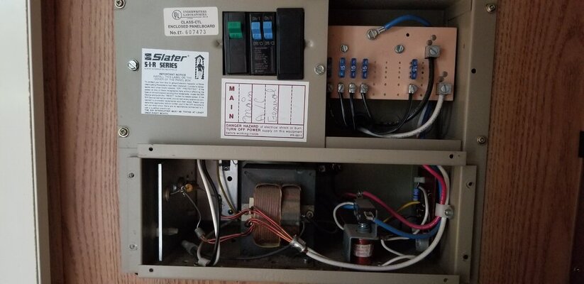
For starters, I did the 12v+ wires on the bottom of the Progressive Dynamics fuse panel I had installed over a year ago when I swapped out the converter.

After doing these, I decided to re do the nasty mess at the 12v DC ground bar that is mounted to the floor behind the power panel. The bar was mounted horizontally on a metal Z bracket and that made access to the screw heads difficult with a screwdriver, and an unsightly mess of wires arched up and over to the openings in the bar.

In every case, I cut off the bare end of the wire and stripped it and fitted a ferrule to the wire and crimped it.

I went to Home Depot and bought a section of ½ x ¾ aluminum extrusion and cut and drilled it and smoothed the edges, which allowed me to remount the ground bar vertical, allowing easy access to the screws and allowing the wires to lay flat on the floor, reducing the strain on the wires at the bar. Pictures tell the story.

A trailer or motor home traveling down the road is like your home going thru a magnitude 7 earthquake all the time. All electric and plumbing connections should be checked for tightness every year or so depending on the frequency of use.

The use of ferrules will provide for a “crush proof” connection that will stay tight, while soft copper wire will shake and work, then weaken and break, or compress until it becomes loose.

Though the pictures do not show it, I eventually went back in and cut and stripped the wires on the top of the 12v fuse panel, including the solder tinned converter wires, and installed ferrules on them.

One of the terminals on the fuse panel, the BATT+ terminal had an 8 gauge wire in it, from the battery relay; and also had a 10 gauge wire (charge line) from the 7 pin umbilical that plugs into the tow vehicle. This wire supplied a circuit breaker next to the battery relay and then ran parallel to the 8 gauge battery wire and connected to the same terminal on the fuse panel as the battery wire did. You cannot put two different size wires with ferrules in one connector, it won’t tighten down on the smaller one.

I realized the 5 ft run of 10 gauge was redundant as this wire only serves to charge the battery while driving, and I disconnected both ends of the wire and installed a 6 inch jumper from the circuit breaker to the terminal on the battery relay. Now the electricity travels thru about 10 ft less wire than before to charge the battery, and I only have one wire to deal with in the Battery + terminal on the top of the fuse panel. I checked voltages and circuits to insure I wasn’t doing something wrong. Not sure why BF chose to run the wire the way they did.

To be clear, this change in wiring has no effect on outside trailer lights (brake, running, backup) electric brake circuits, etc, nor does it affect in any way, the operation of ANY 12v DC circuit, it merely shortens the electrical path for charging the trailer’s battery from the tow vehicle.

I hope this gives someone an idea of what ferrules are and how they can be used to neaten electrical wiring and connections, and insure better connections.

Square crimp tool for ferrules

Amazon.com

Hex crimp tool for ferrules

https://www.amazon.com/gp/product/B07MZXWTVQ/ref=ppx_yo_dt_b_asin_title_o06_s01?ie=UTF8&psc=1

A good source of ferrules, both insulated and non-insulated, crimpers, electrical terminals of all kinds and other electrical items Ferrules Direct
 

Attachments

  • j813a-Ferrule-inst-ground-bar-before.jpg
    j813a-Ferrule-inst-ground-bar-before.jpg
    316.1 KB · Views: 3
  • g6d40-Ferrule-inst-ground-wires-with-strands-flayed-out.jpg
    g6d40-Ferrule-inst-ground-wires-with-strands-flayed-out.jpg
    330.4 KB · Views: 3
  • wiy0j-Ferrule-inst-ground-bar-remounted-on-L-extrusion.jpg
    wiy0j-Ferrule-inst-ground-bar-remounted-on-L-extrusion.jpg
    365.2 KB · Views: 3
  • h8jdr-Ferrule-inst-ground-bar-inst-completed.jpg
    h8jdr-Ferrule-inst-ground-bar-inst-completed.jpg
    355 KB · Views: 3
  • 6znj0-Ferrule-inst-dc-fuse-panel-blown-fuse-indicator.jpg
    6znj0-Ferrule-inst-dc-fuse-panel-blown-fuse-indicator.jpg
    338.9 KB · Views: 3
Just finished installing. Phew, must have double jointed young little people to install. it is at the floor against a wall and the angle countertop is above it, in a truck camper floorplan. I'll post. I tinned all the leads before connecting. Tested my 12v circuits. Fan and water pump worked fine. drinking more water, then go back and connect battery. Phew. Pretty much the last task before we can head out. (I think). Towdolly all set, brakes, lights, bearings... Added an uax battery to the truck, OK, that is another task, wiring thru the isolator. I think I will add a knife switch for storage though.
 
Aux battery and isolator now installed. Working on pumping some lube into the hubs on tow dolly. New one on me. not sure it is working.

OK RTFM! pumping lube now. Tomorrow, will move it back to storage but heading out early next week for a few days. Heading higher and cooler.
 
Last edited:
Old nasty looking dolly like that, Bearings are an unknown, I'd be pulling them apart and at the very least inspecting them after a good cleaning and then repacking, but if they say CHINA on them, I just chuck them.

Charles
 

Latest posts

Forum statistics

Threads
132,446
Posts
1,395,427
Members
138,132
Latest member
OhDis
Back
Top Bottom